온프레미스 자산을 클라우드 솔루션으로 마이그레이션하는 것은 복잡한 과정일 수 있으며, 특히 기존 IP 주소 계획을 고려할 때 더욱 그렇습니다. Azure VMware Solution(AVS)으로 마이그레이션하는 주요 이점 중 하나는 기존 IP 주소를 유지할 수 있다는 점입니다. 이를 통해 마이그레이션 프로세스를 간소화하고 다운타임을 줄일 수 있습니다. 하지만 이러한 접근 방식은 원활한 전환을 위해 신중한 계획과 네트워크 원칙 고려가 필요합니다.
이 게시물에서는 AVS로 마이그레이션하는 동안 IP 주소를 유지하기 위한 몇 가지 고려 사항을 살펴보겠습니다. 여기에는 네트워크 종속성을 이해하는 것의 중요성과 성능에 미치는 잠재적 영향이 포함됩니다. 또한 VMware Hybrid Cloud Extension(HCX) 레이어 2 확장 기능을 활용하여 마이그레이션 프로세스를 원활하게 진행하는 이점도 논의합니다.
일반적인 고려 사항
무엇보다도, 솔루션을 모색하기 전에 몇 가지 기본적인 네트워크 원칙을 정립해야 합니다. Azure VMware Solution(AVS)으로 마이그레이션을 계획하고 기존 IP 주소를 유지할 때 이러한 원칙을 이해하는 것이 매우 중요합니다. IP 여정의 기대치에 맞춰 네트워킹 원칙을 재구축할 수는 없기 때문입니다.
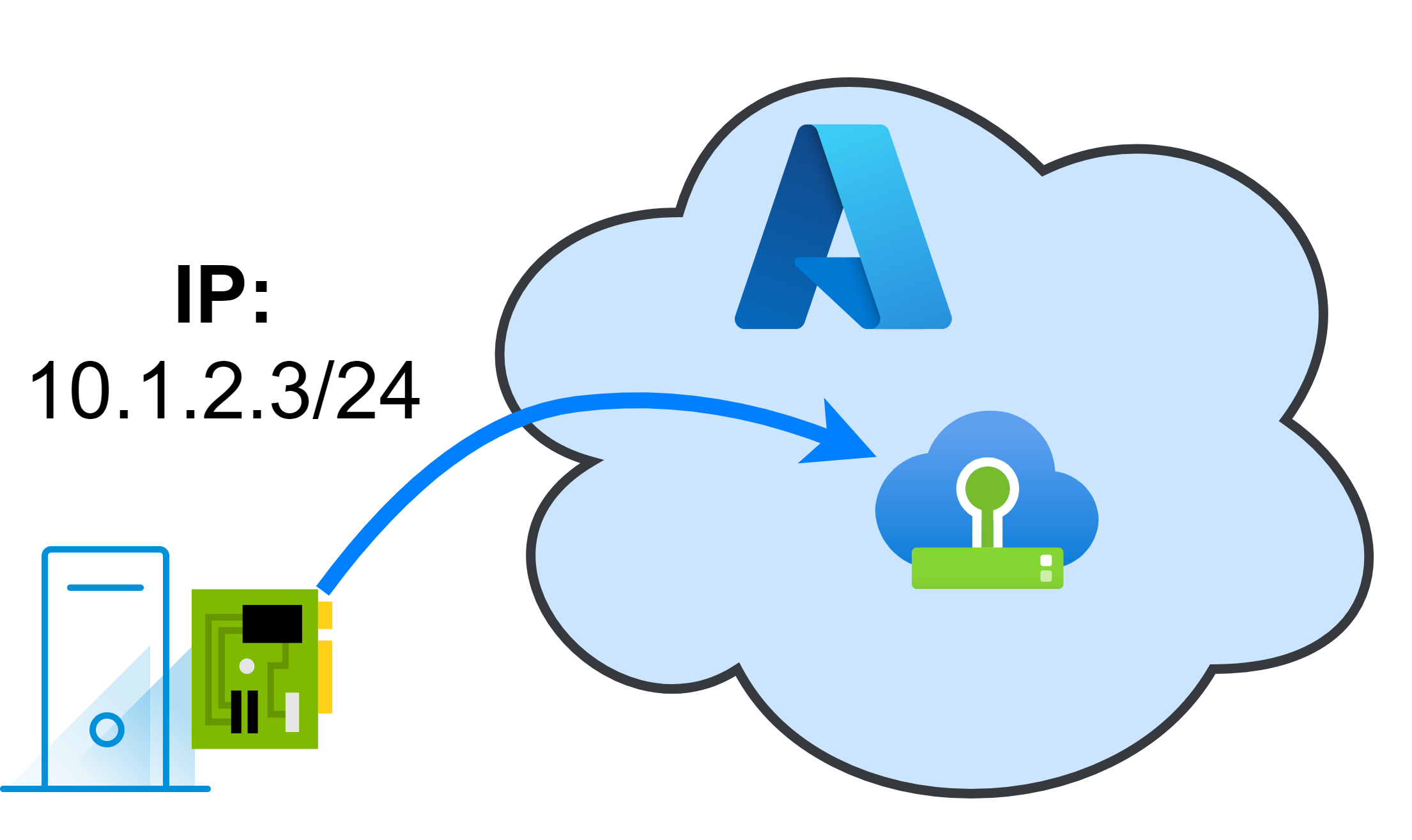
단일 라우팅된 네트워크는 한 위치에서만 액세스할 수 있습니다.
당연한 것처럼 들리지만, 라우팅된 네트워크는 한 번에 한 위치에서만 액세스할 수 있다는 점을 이해하는 것이 중요합니다. 즉, 온프레미스 환경에 라우팅된 네트워크(예: 10.1.2.0/24)가 있는 경우, 동일한 IP 주소 범위를 가진 네트워크를 클라우드 측에서 동시에 게시할 수 없습니다. 이는 네트워킹의 기본 원칙이며 마이그레이션을 계획할 때 반드시 고려해야 합니다.

단일 vLAN의 자산은 동일한 브로드캐스트 도메인을 공유합니다.
자산이 동일한 VLAN에 있으면 동일한 브로드캐스트 도메인을 공유합니다. 즉, 라우터 없이도 서로 통신할 수 있습니다. 이는 확장된 L2 네트워크의 자산에도 적용됩니다.
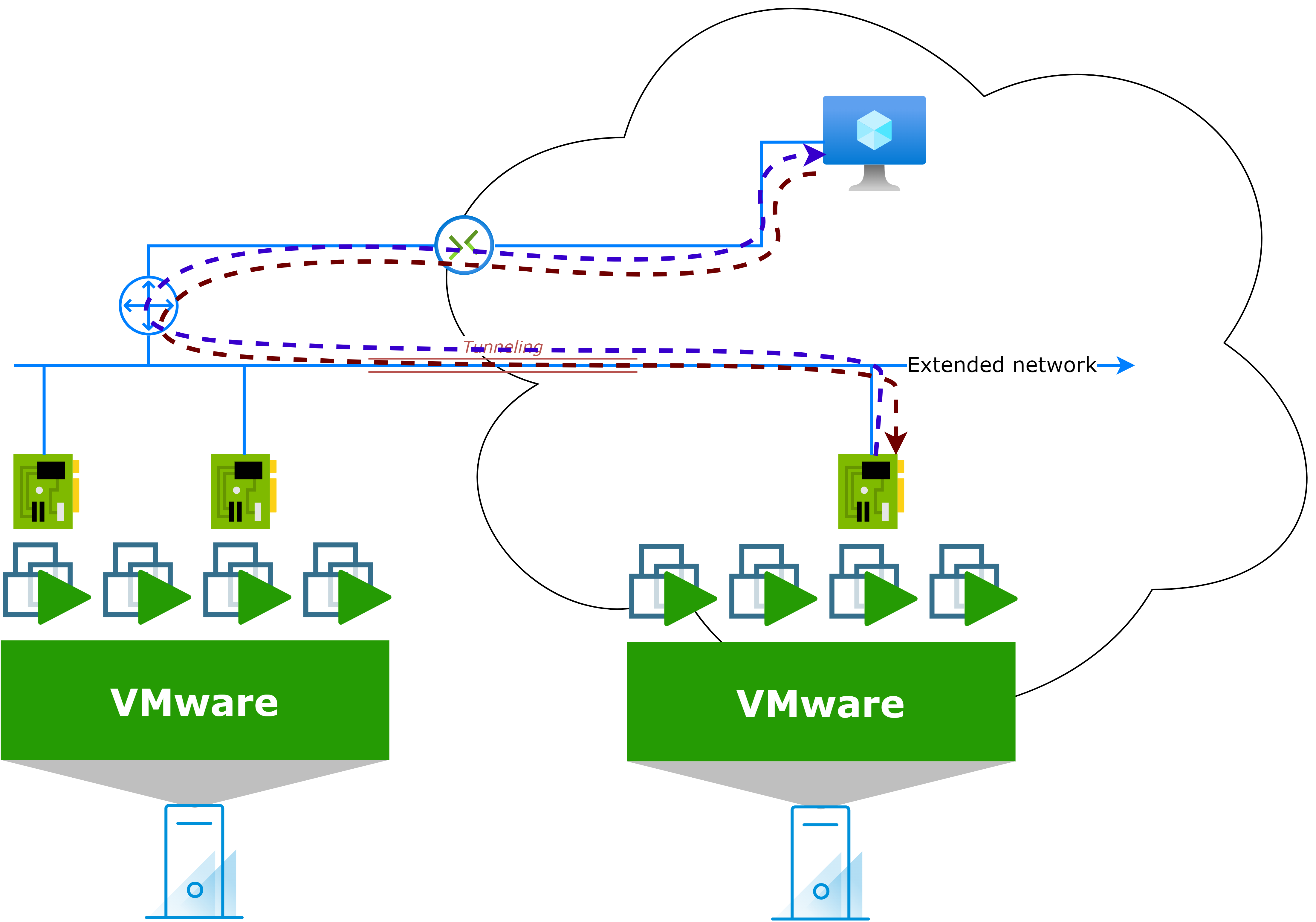
확장된 L2 네트워크를 통한 ARP 브로드캐스트의 예:

마이그레이션된 자산은 구성된 게이트웨이를 계속 사용하여 라우팅된 피어에 도달합니다.
자산을 클라우드로 마이그레이션하고 IP 주소를 유지하면 구성된 게이트웨이를 계속 사용하여 라우팅된 피어에 접속합니다. 즉, 온프레미스 환경에 라우팅된 네트워크가 있는 경우, 마이그레이션된 자산은 온프레미스 게이트웨이를 사용하여 동일 네트워크의 다른 자산과 통신합니다. 일반적으로 이 연결 경로는 송신 및 수신 트래픽 모두에 사용됩니다.

마이그레이션된 자산과 마이그레이션되지 않은 자산 사이에 지연이 발생합니다.
자산을 클라우드로 마이그레이션하고 IP 주소를 유지하는 경우, 마이그레이션된 자산과 마이그레이션되지 않은 자산 간에 지연 시간이 발생합니다. 익숙한 온프레미스 연결 외에도 다음과 같은 여러 요인이 지연 시간에 영향을 미칩니다.
- 두 위치 사이의 지리적 거리
- 링크 품질 및 라우팅 홉
- 링크 사용 및 혼잡
- 터널링 기술 및 프로토콜 사용
- 교통의 트롬보닝 가능성

확장된 L2 네트워크의 경우 트래픽 지연은 클라우드 간 통신에 영향을 미칠 수도 있습니다. 이를 트롬보닝 효과라고 합니다.
트래픽 트롬보닝이란 무엇인가요?
교통 트롬보닝은 교통이 직선 경로로 이동하지 않고 한 장소에서 다른 장소로 이동한 후 다시 돌아올 때 발생합니다.
예: 최악의 시나리오 중 하나는 클라우드에서 마이그레이션된 자산이 다른 네트워크의 다른 자산과 통신을 시도하는 경우입니다. 한 자산의 게이트웨이가 온프레미스에 있는 경우, 트래픽은 마이그레이션된 자산(클라우드 측)에서 온프레미스 게이트웨이로 이동한 후 다시 클라우드 측으로 이동하여 대상 자산에 도달합니다. 응답은 대상 자산(클라우드 측)에서 온프레미스 게이트웨이로, 마지막으로 마이그레이션된 자산으로 돌아오는 동일한 경로를 따릅니다.
이 패턴은 성능과 인지된 지연 시간에 큰 영향을 미칠 수 있습니다.
IP 주소를 유지하기 위해 네트워크 확장
이미 추측하셨겠지만, 클라우드 솔루션으로 마이그레이션하는 동안 IP 주소를 유지하기 위한 솔루션은 네트워크를 확장하고 VM/애플리케이션 또는 다른 종류의 자산이 아닌 "네트워크별" 마이그레이션을 고려하는 것입니다.
일을 제대로 하려면 다음과 같은 방법을 권장합니다.
실행 계획
- 계획, 계획, 계획!
- 확장할 네트워크를 신중하게 선택하세요.
- 다음 단계를 이해하고 네트워크를 확장하여 이를 실행하는 방법을 알아보세요.
- 네트워크의 모든 종속성을 이해합니다.
- L2 네트워크 확장
- 이제 네트워크는 두 위치에 자산을 호스팅할 수 있습니다.
- 게이트웨이는 온프레미스(대부분의 자산)에 유지됩니다.
- 자산 마이그레이션
- 마이그레이션된 자산은 연결성과 IP 주소를 유지합니다.
- 남은 자산 대피
- 필요한 경우: 일부 자산에는 네트워크가 온프레미스 리소스로부터 자유로운지 확인하기 위해 reIP가 필요할 수 있습니다.
- 스위치오버 연결
- 이제 연결성이 클라우드 쪽으로 전환되었습니다.
- 모든 워크로드는 기본 연결을 사용합니다.
- L2 확장이 제거되었습니다.
마이그레이션 프로젝트와 관련하여 실행 계획의 각 단계에는 고유한 중요도 수준이 있으며, 다음과 같이 요약할 수 있습니다.
| 계획 | 비판적인 |
| L2 네트워크 확장 | 낮은 |
| 자산 마이그레이션 | 중간 |
| 남은 자산 대피 | 낮은 |
| 스위치오버 연결 | 비판적인 * |
* 계획 단계에 따라 크게 달라집니다.
어떻게 작동하나요?
네트워크 확장이 작동하는 방식을 간략하게 나타낸 다이어그램은 다음과 같습니다.

신중한 계획 후:
- 네트워크 확장은 확장 기술을 사용하여 구현됩니다(예시는 나중에 제공).
- 이 네트워크의 자산은 마이그레이션(IP 주소 유지)되거나 네트워크에서 철수(재IP, 폐기 등)됩니다.
- 네트워크 확장이 제거되고 연결이 클라우드 쪽으로 전환됩니다.
현재 내 네트워크는 어떻게 구성되어 있나요?
마이그레이션을 계획할 때는 현재 네트워크가 어떻게 구축되어 있는지, 그리고 마이그레이션 프로젝트에 대한 목표가 무엇인지 이해하는 것이 중요합니다. 이를 통해 잠재적인 문제를 파악하고 성공적인 마이그레이션을 계획할 수 있습니다.
| VMware 자산만 있는 소규모 Layer 2(L2) 서브넷. | 평평한 네트워크 토폴로지. |
| 모든 자산이 클라우드로 마이그레이션됩니다. | 모든 리소스가 클라우드로 전환되는 것은 아닙니다. |
| 네트워크와 자산 간의 네트워크 종속성을 잘 이해합니다. | 네트워크 종속성에 대한 지식이 제한적입니다. |
| 마이그레이션 후 온프레미스와의 종속성이 없습니다. | 마이그레이션 후 온프레미스와의 종속성이 많아졌습니다. |
최상의 시나리오와 최악의 시나리오 기준을 쉽게 결정할 수 있다면, 이 두 극단적인 시나리오 사이에는 온갖 가능성이 존재할 수 있습니다 .
위험 완화
다음 섹션에서는 이전 위험에 대한 몇 가지 가능한 완화 전략을 살펴보겠습니다.
VMware 및 비 VMware 자산을 포함하는 네트워크
- 네트워크별로, 한 범주 또는 다른 범주를 재IP화하는 데 드는 노력의 수준을 고려하세요. 예:
- 자산의 80%가 온프레미스에 남습니다. 마이그레이션된 20%의 IP 주소를 변경해야 합니까?
- 자산의 80%가 클라우드로 마이그레이션됩니다. 온프레미스에 남아 있는 20%의 IP 주소를 변경해야 합니까?
- 마이그레이션된 워크로드에 대한 재IP 전략을 고려하는 경우에도 L2 확장은 여전히 리소스 마이그레이션에 도움이 될 수 있습니다.
마이그레이션 후 온프레미스와의 종속성
- 온프레미스에서 호스팅되는 서비스(PaaS/IaaS 등)의 클라우드 마이그레이션을 고려하세요.
- 환경 간에 연결 방법을 조정합니다. 대역폭을 늘리고 지연 시간을 줄입니다.
네트워크 종속성에 대한 지식이 제한됨
- Azure Migrate는 네트워크 및 자산의 모든 종속성을 매핑하는 데 도움이 될 수 있습니다 .
- VMware Aria Operations for Networks 와 같은 다른 도구 .
VMware 하이브리드 클라우드 확장(HCX)
VMware HCX는 Azure VMware Solution(AVS)으로 마이그레이션하는 동안 네트워크를 확장하고 IP 주소를 유지하는 데 도움이 되는 강력한 도구입니다. 기존 IP 주소를 유지하면서 워크로드를 원활하게 마이그레이션할 수 있는 방법을 제공하여 마이그레이션 프로세스를 간소화하고 다운타임을 줄일 수 있습니다.
HCX Enterprise는 AVS용 무료 추가 기능 으로, 추가 비용 없이 온프레미스에서 AVS로 워크로드를 마이그레이션하는 데 사용할 수 있습니다.
HCX L2 확장을 위해 고려해야 할 전제 조건
| (표준) vSwitch는 HCX에서 L2 네트워크 확장을 지원하지 않습니다. → Distributed-vSwitch 로 마이그레이션을 고려해 보세요. |
|
| NSX-V에서 NSX-T로의 마이그레이션에 대한 HCX 지원은 버전 4.11에서 더 이상 지원되지 않습니다. |
|
| HCX는 제한된 지원으로 vSphere 및 vCenter 6.5에 대한 마이그레이션을 지원합니다. |
|
HCX 모빌리티 최적화 네트워크(MON)를 통한 교통 트롬보닝 완화
HCX 사용의 주요 이점 중 하나는 네트워크 트래픽을 최적화하고 지연 시간을 줄이는 기능입니다. HCX 모빌리티 최적화 네트워크(MON)는 마이그레이션된 자산과 마이그레이션되지 않은 자산 간 또는 다른 네트워크의 리소스 간 트래픽 경로를 최적화하여 트롬보닝 효과를 최소화하는 기능입니다.
이전 게시물( VMware HCX: MON으로 이동 및 복귀 )에서는 HCX MON이 작동하는 방식과 트롬보닝 효과를 크게 줄이도록 구성하는 방법을 살펴보았습니다.

NSX 자율 엣지
HCX에 대한 또 다른 접근 방식은 NSX Autonomous Edge(NSX AE)를 사용하여 네트워크를 확장하고 Azure VMware Solution(AVS)으로 마이그레이션하는 동안 IP 주소를 유지하는 것입니다. 이 접근 방식은 NSX-T VPN 기능을 사용하여 온프레미스 환경과 클라우드 환경 간에 터널을 생성하므로, 워크로드를 마이그레이션하는 동안 네트워크를 확장하고 IP 주소를 유지할 수 있습니다.
참고: NSX AE에서는 표준 vSwitch가 지원됩니다.
NSX L2 확장을 위해 고려해야 할 전제 조건 및 제한 사항
여러 VLAN을 확장하려면 트렁크 인터페이스가 필요합니다.
|
|
| HCX MON과 같은 최적화가 없습니다. | 마이그레이션이 완료되면 즉시 네트워크 확장 전환을 권장합니다. |
| NSX AE OVF를 다운로드하려면 Broadcom 권한이 필요합니다. | 해당 없음 |
결론
결론적으로 Azure VMware Solution(AVS)으로 마이그레이션하는 동안 IP 주소를 유지하는 것은 복잡한 프로세스가 아니지만 신중한 계획과 네트워크 원칙 고려가 필요합니다 .
VMware Hybrid Cloud Extension(HCX) Layer 2 확장 기능이나 NSX Autonomous Edge를 활용하면 마이그레이션 프로세스를 간소화하고 기존 IP 주소를 유지하면서 가동 중지 시간을 줄이거나 방지할 수 있습니다.
'IT이야기 > Azure' 카테고리의 다른 글
| VMware HCX: MON으로의 복귀 (1) | 2025.04.15 |
|---|---|
| Azure VMware Solution 스토리지를 확장하기 위한 Azure Elastic SAN (0) | 2025.04.15 |
| Azure VMware 솔루션 – NSX-T Edge에서 공용 IP 사용 (0) | 2025.04.15 |
| Azure 비용 최적화: Azure 비용을 절감하는 12가지 방법 (0) | 2025.04.11 |
| *자본 비용(CAPEX)*과 *운영 비용(OPEX)*은 IT 인프라 투자나 클라우드 이전(Assessment 포함)에서 반드시 구분해야 할 핵심 개념. (1) | 2025.04.08 |


