728x90

This blog post should have been posted quite some time ago, however, after numerous revisions and the details in the post, you’ll understand why.

In this post I will demonstrate creating a converged network fabric in SCVMM 2012R2. This converged network will consist of logical network adapters, QoS, NIC (vNIC) teaming, and network adapters.

Step 1, Understand your infrastructure

To begin, my environment is using a Cisco UCS (B200 M4) back end, with Cisco Nexus 9K switches and of course Hyper-V (Windows 2012R2) as its hypervisor. The UCS profile used here, has been provisioned with 7 vNICs and dedicated VLANs for each vNIC to isolate the traffic between the networks. The 7 vNICs for the following jobs (see below). All vNICS have a 10GB interface.

  1. iSCSI-A (traffic to the SAN controller 1)
  2. iSCSI-B (traffic to the SAN controller 2)
  3. CSV-Heartbeat
  4. Live Migration
  5. Management
  6. Server-A (VM Production traffic)
  7. Server-B (VM Production traffic)

Server-A and Server-B vNICs we will team, but we will get into that later.

Step 2, we need understand what all these vNICs are intended for. The logical networks below illustrate the purpose of each network.

  1. SAN/Storage (1) (iSCSI-A) – This network will be for access storage via iSCSI on SAN controller 1. In this environment, we will have two VLANs for redundancy, thus two iSCSI networks.
  2. SAN/Storage (2) (iSCSI-B) – see above. This network will be for access storage via iSCSI on SAN controller 2.
  3. Live Migration – This network will be communication between the hypervisors to transfer VM memory, states, etc.
  4. CSV/Heartbeat – This network will be used by the cluster to communicate a healthy (online) state of the environment.
  5. Management – This network will be used to manage the Hyper-V/hypervisors. SCVMM will make use of this network to communicate to the Hyper-V nodes.
  6. VM Traffic (Server-A + Server-B) – This network will be intended communication for VMs and VMs only. This will be not only a redundant network, but a teamed network to allow additional I/O throughout. As mentioned, all vNICs are on a 10GB interface, teaming these two vNICs/networks will allow I/O to operate at 20GB/s.

Please refer to Microsoft article further details, HERE.

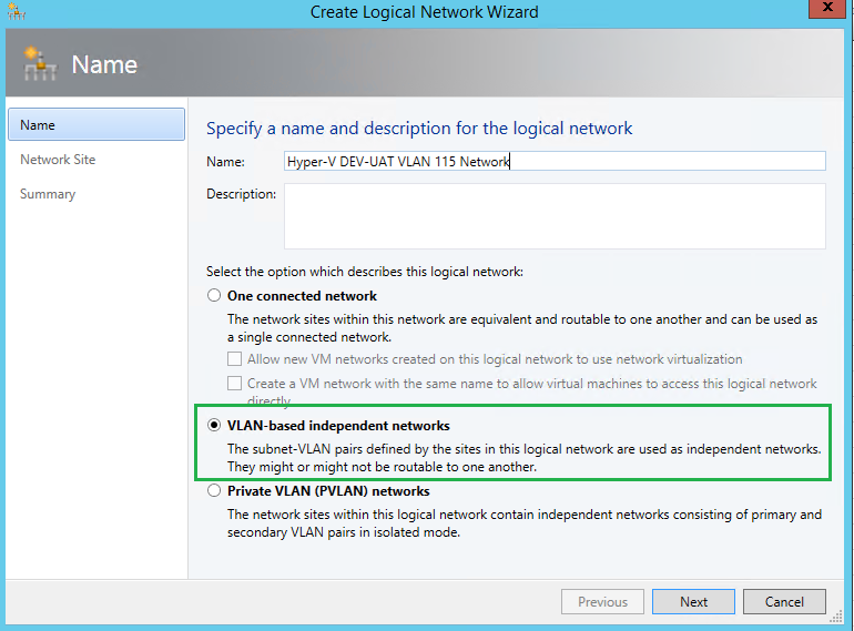
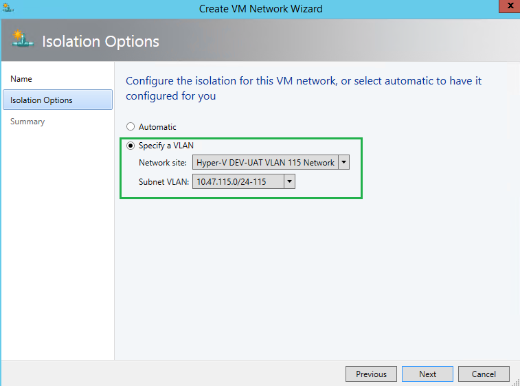
Step 3, SCVMM – Create Logical Network(s)

Within SCVMM, you will now need to create your logical networks within the Fabric pane. As mentioned, I am using VLANs to isolate my traffic. I am also planning to have 15 VM network environments with each having its own dedicated VLAN, VLAN 101 through 116, ie. 10.47.101-116.x. Likewise, dedicated VLANs for iSCSI, Live Migration, etc.

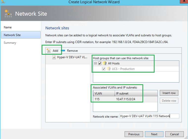
Here you need to specify the IP subnet and VLAN ID, and apply it to your Host(s) group.

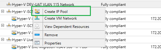
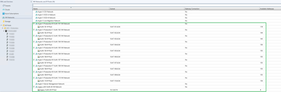
Step 4, SCVMM – Create IP Pool(s)

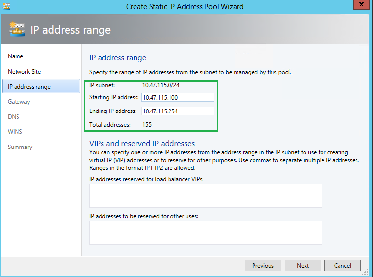
Once you create all of your logical networks, you can now create IP Pools. IP Pools will allow you to manage your logical network, and ensure there are no duplicate IPs consumed. You can also reserve IPs for VIPs, etc. In the screenshot below, as you can see, within my “Production” VM network traffic, my IP range states at 10.47.101.100/24 and ends at 10.47.101.252. This allows 155 IPs to be used. If the IP Pool is soon to be exhausted, this setting configuration can be changed to increase the scope. But for now, I know 155 IPs is more than enough.

By right-clicking on the Logical Network you just created, select “Create IP Pool“.

You will need to bound the IP Pool to the Logical Network.

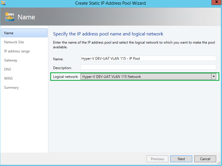
Choose, “Use an existing network site” and ensure the right network site and IP subnet populated.

Here, I am defining a range of IPs for my Pool. Although I know 155 IPs are more than enough, and will never need all 254 IPs, I am comfortable with the range starting at 100.

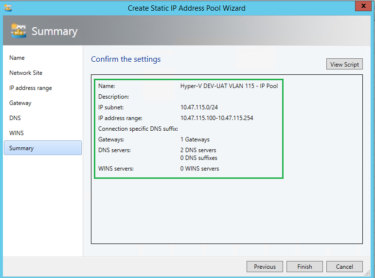
As you can see here, I have also specified the Gateway and provided 2 DNS servers for the IP Pool. When a new VM will be created, all of the IP Properties will be pulled from here and populated once the VM has been built.

At the end of all this, your Logical Network Fabric could look something like this, with your Logical Networks and IP Pools per network.

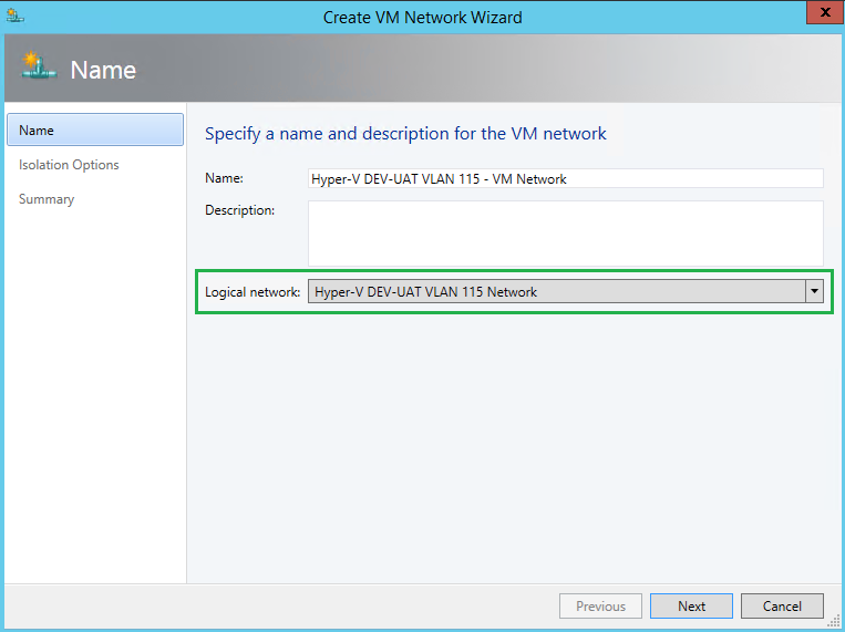
Step 5, SCVMM – Create VM Networks + IP Pools

Within the VMs and Services pane, we will now need to create VM networks. This will be assoicated to our Logical Networks we just created. Within the creation process, we will need to specify the Logical network bound to this VM network. Here I created IP Pools again. I find this process of IP Pools a bit odd/redundant. I have IP Pools in both the Logical Network and the VM Network.


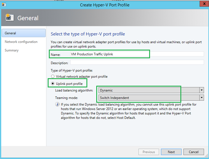
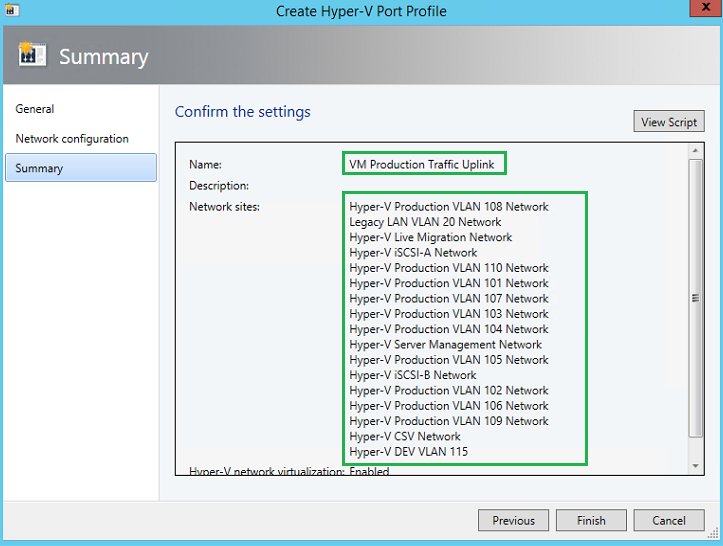
Step 6, SCVMM – Creating Uplink Port Profile

Now we need to create the Uplink Port Profile for our VM Production Traffic. Unfortunately with SCVMM 2012 R2 UR8, SCVMM does not come with a default Uplink port profile, so we must create one. Microsoft best practice indicates using a Dynamic and Switch Independent for the Hyper-V workload.

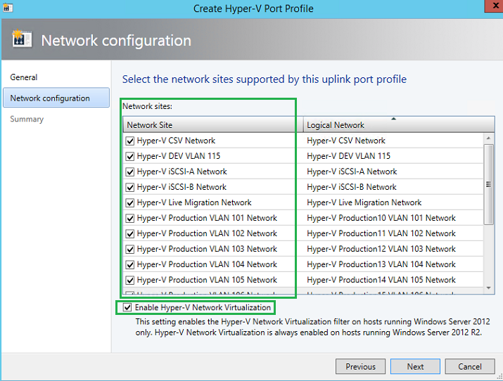
Now we will need to bound all the networks we previous created to the Uplink Port Profile. Here VMM will tell the hypervisors how they are connected and mapped to the network fabric. iSCSI traffic, Live Migration, VM Production, CSV-Heartbeat, etc.


Step 7, SCVMM – Create Logical Switch

Now we will create the logical switch, or also known as a vSwitch. The logical switch is the last part of the fabric puzzle. This logical switch will contain the Uplink Port Profile along with the Virtual port profiles (if we chose to manage QoS via SCVMM).

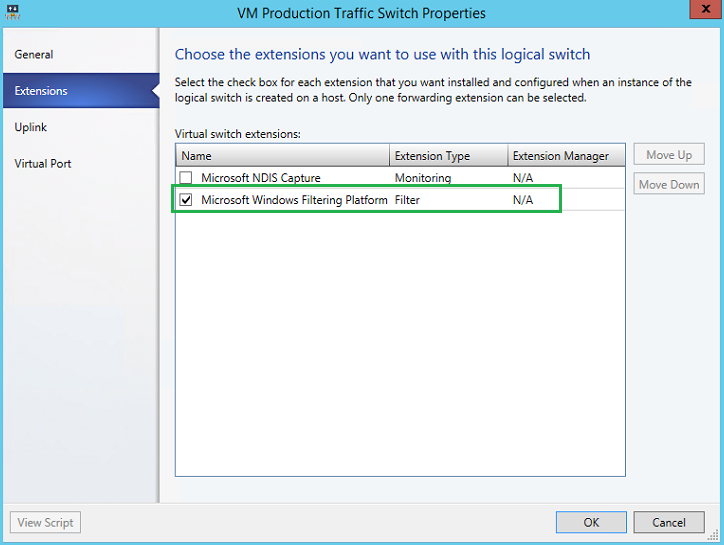
Within the Logical Switches – Fabric, we will create a new Logical switch. In my scenario, I have not made use of SR-IOV (Single Root – Input Output Virtualization).

We will use the default Microsoft Windows Filtering Platform for our vSwitch extension.

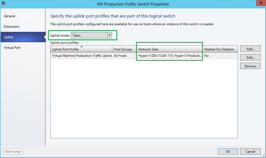
Here will will specify the uplink port profile(s) that will be associated to the logical switch.  We will Team the mode, and add our Production Uplink/Network sites.

We will need to specify the port classifications for each virtual port for the logical switch. Here you can see we are using three classes, high, medium and low bandwidth. 

Step 8, SCVMM – Assign Logical Switch to Hypervisor

Finally, we now need to assign the logical switch to our hypervisor(s). Navigate to (each) the host group within the fabric work-space and within each hypervisors properties, navigate to the Virtual Switches. Select “New Virtual Switch“. Here we will specify which (in our case only 1) Uplink port profile to use on the physical adapter. Since my two vNICs will be teamed, I will have two (2) adapters bound to the same Uplink port profile.


Now you are ready to start building machines, making use of your network fabric, and maximizing System Center Virtual Machine Manager 2012R2’s  power.


If you have any questions, please drop me a line, and/or need some guidance.

728x90
728x90

This blog post will focus on deploying Storage Spaces Direct (S2D) with Windows Server 2016 (steps with Server 2019 should be very-very similar, if not exact…) in a RoBo (Remote Office Branch Office) configuration with Dell Ready Nodes (S2DRN) leveraging RDMA (Remote Direct Memory Access). Now that is a mouthful, so let’s focus on what is Storage Spaces Direct first.

What is Storage Spaces Direct? With Server 2016, Microsoft introduced Storage Spaces Direct (S2D) with the release of Server 2016. S2D allows you to take industry-standard servers and leverage the internal local drives within the nodes and create a highly-available, highly-scalable software defined storage. Using hyper-converged or converged architecture, you are able to quickly deploy, scale storage, while implementing features such as storage tiers, caching, all while taking advantage of RDMA networking.

What is RDMA? Remote Direct Memory Access, or in short, RDMA, is an enterprise networking technology that allows you to exchange data through memory, without consuming the CPU or Operating System kernel. RDMA allows your applications to have high IOPS and with very low latency, while leveraging either RoCe (RDMA over Converged Ethernet) or iWARP (Internet Wide Area RDMA Protocol).

Note: the steps below focus on a single node of a 2-node cluster. All the steps below need to be executed on the secondary node.


Network Connectivity

Before we begin implementing, deploying and configuring we need to plan out the networking connectivity design. However before we do that, we need to understand what our design will look like. Below is a high-level diagram that illustrates the network connectivity for the host management and VM traffic, and the RDMA (Storage) traffic.


Network Configuration

Next we should map out our IP configuration. With this 2-node deployment we know we need the following network adapters and the following IPs.

Traffic Class Purpose Minimum IPs required VLAN ID Tagged/Untagged IP Address Space VLAN IP Address
Out of Band (iDRAC) Remote Management 2   Untagged /29  
Management (Host) Management of Cluster and Cluster Nodes 3   Tagged/Untagged /29  
Storage 01 SMB Traffic 2   Tagged/Untagged /29  
Storage 02 SMB Traffic 2   Tagged/Untagged /29  

Now that we have defined our networking configuration, we can move forward with booting the nodes, and making some necessary changes to the BIOS.


BIOS Configuration

Launch the node, and log into the BIOS (usually F2 at the Dell prompt)… Next go to the Device settings and let’s configure the RDMA/QLogic adapters.

Your configuration should look similar to this. In my instance, I am leveraging iWARP and not RoCE. By default, the adapters will allow for both modes, but we want to force iWARP only.

Disable Virtualization Mode

Disable DCBX (Data Center Bridging)

  • Link Speed: SmartAN
  • NIC + RDMA Mode: Enabled
  • RDMA Operation Mode: iWARP
  • Virtual LAN ID: 1 (which is default)

Remember, this needs to be done to both RDMA adapters!!! Once the settings have been applied, and saved, go ahead and reboot the node. Remember to do the second node too!


Install & Update Operating System

Next, we now need to install the Operating System. As best practice, once the OS is installed, update the OS and update all network drivers.


Validate & Rename Network Adapters

Also, it is a good idea to rename the Network adapters. Before we do that, let’s just confirm the adapters are there and look right.

1
Get-NetAdapter


Install Windows Features & Roles

Once the OS has been installed, and patched. Next we now need to install the necessary roles and features, ie. Hyper-V, Failover Manager, etc.

1
Install-WindowsFeature -Name Hyper-V, Failover-Clustering -IncludeAllSubFeature -IncludeManagementTools -Verbose -Restart

Configure Host Network

Now we need to configure the host management network. In this step we will create a SET switch (Switch Embedded Teaming). This switch will not only team the two network (host) adapters but at the same time a SET switch will be created that will be leveraged by the guest VMs via Hyper-V.

1
New-VMSwitch -Name S2DSwitch -AllowManagementOS 0 -NetAdapterName 'NIC1','NIC2' -MinimumBandwidthMode Weight -Verbose

Within this code, note, NIC1 and NIC2 are the host management adapters that were renamed to make life easier.

Now we need to create and configure the host management adapter. We will do this by executing the following cmdlet. Please note, in my environment, the Host Management network is untagged.

1
Add-VMNetworkAdapter -ManagementOS -Name 'Management' -SwitchName S2DSwitch -Passthru | Set-VMNetworkAdapterVlan -Untagged –Verbose

Once we execute this command, and run the Get-NetAdapter cmdlet, we can now see we have an additional network adapter.

In the event you need to tag your Management adapters you can use the following cmdlet below as reference.

1
2
Set-NetAdapterAdvancedProperty -Name 'SLOT 3 PORT 1' -DisplayName 'VLAN ID' -DisplayValue 103 -Verbose
Set-NetAdapterAdvancedProperty -Name 'SLOT 3 PORT 2' -DisplayName 'VLAN ID' -DisplayValue 104 -Verbose

Great, now we can add the nodes to the domain, and set the Management network adapters with static IPs.


Create the Cluster, Configure Witness, Enable Storage Spaces Direct

Now that are nodes are domain joined, and static IPs have been applied to the host management network, we can now begin creating the cluster.

In the code below, I am going to create the cluster; add the two nodes to the cluster; provision the Quorum witness (file witness) and enable Storage Spaces Direct on the cluster.

1
2
3
4
5
6
$cluster="Cluster_Name"
New-Cluster -name $cluster -Node "node01", "node02" -StaticAddress "IP Address" -NoStorage -Verbose
#assign cluster quorum
Set-ClusterQuorum -Cluster $cluster -FileShareWitness "\\server\filewitness\UNCPatch"
#enable storage spaces direct
Enable-ClusterS2D -Verbose

Once we have executed the commands above, if we launch Failover Manager, we can now see the created Cluster, with the 2 nodes, and Storage Spaces Direct enabled.


If we go into the Pool, we can also now see our Software Defined Storage Pool. We now can create volumes off of this pool.

If we go into the Enclosures, we can now also see all the disks available within the nodes and all disks that are members of the Storage Pool.

Great, now we need to do some configuration on the RDMA Adapters… Also to note, in this scenario I have leveraged a file share witness for the cluster. I would highly recommend considering or using Azure Cloud Witness. The egress traffic is next to 0, and you can connect several clusters to the storage account. For more information, see the following blog post(s): HERE.


Change RDMA mode to iWARP on QLogic Adapters

Again, remember which RDMA adapter is which. As mentioned previously, I renamed all of the network adapters to keep things simple and easy to remember.

1
2
Set-NetAdapterAdvancedProperty -Name 'SLOT 3 PORT 1' -DisplayName 'RDMA Mode' -DisplayValue 'iWarp'
Set-NetAdapterAdvancedProperty -Name 'SLOT 3 PORT 2' -DisplayName 'RDMA Mode' -DisplayValue 'iWarp'

Now we can leverage the QLogic adapters with RDMA via iWARP for our Storage traffic.


Create Cluster Shared Volumes (CSV)

Now that our cluster is created, nodes have been added, RDMA is configured, we can now create a CSV that will be leveraged by the VMs as their data store. We will do this by creating the CSV with the following cmdlet.

1
New-Volume -StoragePoolFriendlyName "Storage Pool" -FriendlyName "Volume01" -FileSystem CSVFS_ReFS -size 2TB

Now I elected to keep the CSV small with a 2TB volume, however I did have another 3TB to work with.


Update Live Migration

We are almost there, we now need to update the Live Migration network. This will ensure we make use of the RDMA network and not the Management network. We will do this via Failover Manager console.

Also a good idea to rename the networks. As you can see, I have renamed my storage networks to Storage1 and Storage2, and the host management network to Management.

Go to the Failover Manager Console >> Right Click Networks >> Select Live Migration Settings >> deselect the Management network.

\

You may have also noticed, I have configured the networks and their cluster use. Storage networks will be only available for the cluster, and the Management network will be available for both the cluster and client (guest VMs).


Next steps

We have now successfully created a Storage Spaces Direct cluster, leveraging RDMA networking and using the iWARP protocol. We now also created a SET switch that can be leveraged by our VMs as their network adapter. We have now also created a Storage Pool, with a volume dedicated for our VM disks leveraging the Cluster Shared Volume.

Next steps is now to create a VM and leveraging Storage Spaces Direct!

728x90
728x90

This topic describes how to add servers or drives to Storage Spaces Direct.

Adding servers

Adding servers, often called scaling out, adds storage capacity and can improve storage performance and unlock better storage efficiency. If your deployment is hyper-converged, adding servers also provides more compute resources for your workload.

Typical deployments are simple to scale out by adding servers. There are just two steps:

  1. Run the cluster validation wizard using the Failover Cluster snap-in or with the Test-Cluster cmdlet in PowerShell (run as Administrator). Include the new server <NewNode> you wish to add.This confirms that the new server is running Windows Server 2016 Datacenter Edition, has joined the same Active Directory Domain Services domain as the existing servers, has all the required roles and features, and has networking properly configured.
  2. [!IMPORTANT] If you are re-using drives that contain old data or metadata you no longer need, clear them using Disk Management or the Reset-PhysicalDisk cmdlet. If old data or metadata is detected, the drives aren't pooled.
  3. Test-Cluster -Node <Node>, <Node>, <Node>, <NewNode> -Include "Storage Spaces Direct", Inventory, Network, "System Configuration"
  4. Run the following cmdlet on the cluster to finish adding the server:
Add-ClusterNode -Name NewNode

[!NOTE] Automatic pooling depends on you having only one pool. If you've circumvented the standard configuration to create multiple pools, you will need to add new drives to your preferred pool yourself using Add-PhysicalDisk.

From 2 to 3 servers: unlocking three-way mirroring

With two servers, you can only create two-way mirrored volumes (compare with distributed RAID-1). With three servers, you can create three-way mirrored volumes for better fault tolerance. We recommend using three-way mirroring whenever possible.

Two-way mirrored volumes cannot be upgraded in-place to three-way mirroring. Instead, you can create a new volume and migrate (copy, such as by using Storage Replica) your data to it, and then remove the old volume.

To begin creating three-way mirrored volumes, you have several good options. You can use whichever you prefer.

Option 1

Specify PhysicalDiskRedundancy = 2 on each new volume upon creation.

New-Volume -FriendlyName <Name> -FileSystem CSVFS_ReFS -StoragePoolFriendlyName S2D* -Size <Size> -PhysicalDiskRedundancy 2

Option 2

Instead, you can set PhysicalDiskRedundancyDefault = 2 on the pool's ResiliencySetting object named Mirror. Then, any new mirrored volumes will automatically use three-way mirroring even if you don't specify it.

Get-StoragePool S2D* | Get-ResiliencySetting -Name Mirror | Set-ResiliencySetting -PhysicalDiskRedundancyDefault 2

New-Volume -FriendlyName <Name> -FileSystem CSVFS_ReFS -StoragePoolFriendlyName S2D* -Size <Size>

Option 3

Set PhysicalDiskRedundancy = 2 on the StorageTier template called Capacity, and then create volumes by referencing the tier.

Set-StorageTier -FriendlyName Capacity -PhysicalDiskRedundancy 2

New-Volume -FriendlyName <Name> -FileSystem CSVFS_ReFS -StoragePoolFriendlyName S2D* -StorageTierFriendlyNames Capacity -StorageTierSizes <Size>

From 3 to 4 servers: unlocking dual parity

With four servers, you can use dual parity, also commonly called erasure coding (compare to distributed RAID-6). This provides the same fault tolerance as three-way mirroring, but with better storage efficiency. To learn more, see Fault tolerance and storage efficiency.

If you're coming from a smaller deployment, you have several good options to begin creating dual parity volumes. You can use whichever you prefer.

Option 1

Specify PhysicalDiskRedundancy = 2 and ResiliencySettingName = Parity on each new volume upon creation.

New-Volume -FriendlyName <Name> -FileSystem CSVFS_ReFS -StoragePoolFriendlyName S2D* -Size <Size> -PhysicalDiskRedundancy 2 -ResiliencySettingName Parity

Option 2

Set PhysicalDiskRedundancy = 2 on the pool's ResiliencySetting object named Parity. Then, any new parity volumes will automatically use dual parity even if you don't specify it

Get-StoragePool S2D* | Get-ResiliencySetting -Name Parity | Set-ResiliencySetting -PhysicalDiskRedundancyDefault 2

New-Volume -FriendlyName <Name> -FileSystem CSVFS_ReFS -StoragePoolFriendlyName S2D* -Size <Size> -ResiliencySettingName Parity

With four servers, you can also begin using mirror-accelerated parity, where an individual volume is part mirror and part parity.

For this, you will need to update your StorageTier templates to have both Performance and Capacity tiers, as they would be created if you had first run Enable-ClusterS2D at four servers. Specifically, both tiers should have the MediaType of your capacity devices (such as SSD or HDD) and PhysicalDiskRedundancy = 2. The Performance tier should be ResiliencySettingName = Mirror, and the Capacity tier should be ResiliencySettingName = Parity.

Option 3

You may find it easiest to simply remove the existing tier template and create the two new ones. This will not affect any pre-existing volumes which were created by referring the tier template: it's just a template.

Remove-StorageTier -FriendlyName Capacity

New-StorageTier -StoragePoolFriendlyName S2D* -MediaType HDD -PhysicalDiskRedundancy 2 -ResiliencySettingName Mirror -FriendlyName Performance
New-StorageTier -StoragePoolFriendlyName S2D* -MediaType HDD -PhysicalDiskRedundancy 2 -ResiliencySettingName Parity -FriendlyName Capacity

That's it! You are now ready to create mirror-accelerated parity volumes by referencing these tier templates.

Example

New-Volume -FriendlyName "Sir-Mix-A-Lot" -FileSystem CSVFS_ReFS -StoragePoolFriendlyName S2D* -StorageTierFriendlyNames Performance, Capacity -StorageTierSizes <Size, Size>

Beyond 4 servers: greater parity efficiency

As you scale beyond four servers, new volumes can benefit from ever-greater parity encoding efficiency. For example, between six and seven servers, efficiency improves from 50.0% to 66.7% as it becomes possible to use Reed-Solomon 4+2 (rather than 2+2). There are no steps you need to take to begin enjoying this new efficiency; the best possible encoding is determined automatically each time you create a volume.

However, any pre-existing volumes will not be "converted" to the new, wider encoding. One good reason is that to do so would require a massive calculation affecting literally every single bit in the entire deployment. If you would like pre-existing data to become encoded at the higher efficiency, you can migrate it to new volume(s).

For more details, see Fault tolerance and storage efficiency.

Adding servers when using chassis or rack fault tolerance

If your deployment uses chassis or rack fault tolerance, you must specify the chassis or rack of new servers before adding them to the cluster. This tells Storage Spaces Direct how best to distribute data to maximize fault tolerance.

  1. Create a temporary fault domain for the node by opening an elevated PowerShell session and then using the following command, where <NewNode> is the name of the new cluster node:
  2. New-ClusterFaultDomain -Type Node -Name <NewNode>
  3. Move this temporary fault-domain into the chassis or rack where the new server is located in the real world, as specified by <ParentName>:For more information, see Fault domain awareness in Windows Server 2016.
  4. Set-ClusterFaultDomain -Name <NewNode> -Parent <ParentName>
  5. Add the server to the cluster as described in Adding servers. When the new server joins the cluster, it's automatically associated (using its name) with the placeholder fault domain.

Adding drives

Adding drives, also known as scaling up, adds storage capacity and can improve performance. If you have available slots, you can add drives to each server to expand your storage capacity without adding servers. You can add cache drives or capacity drives independently at any time.

[!IMPORTANT] We strongly recommend that all servers have identical storage configurations.

To scale up, connect the drives and verify that Windows discovers them. They should appear in the output of the Get-PhysicalDisk cmdlet in PowerShell with their CanPool property set to True. If they show as CanPool = False, you can see why by checking their CannotPoolReason property.

Get-PhysicalDisk | Select SerialNumber, CanPool, CannotPoolReason

Within a short time, eligible drives will automatically be claimed by Storage Spaces Direct, added to the storage pool, and volumes will automatically be redistributed evenly across all the drives. At this point, you're finished and ready to extend your volumes or create new ones.

If the drives don't appear, manually scan for hardware changes. This can be done using Device Manager, under the Action menu. If they contain old data or metadata, consider reformatting them. This can be done using Disk Management or with the Reset-PhysicalDisk cmdlet.

[!NOTE] Automatic pooling depends on you having only one pool. If you've circumvented the standard configuration to create multiple pools, you will need to add new drives to your preferred pool yourself using Add-PhysicalDisk.

Optimizing drive usage after adding drives or servers

Over time, as drives are added or removed, the distribution of data among the drives in the pool can become uneven. In some cases, this can result in certain drives becoming full while other drives in pool have much lower consumption.

To help keep drive allocation even across the pool, Storage Spaces Direct automatically optimizes drive usage after you add drives or servers to the pool (this is a manual process for Storage Spaces systems that use Shared SAS enclosures). Optimization starts 15 minutes after you add a new drive to the pool. Pool optimization runs as a low-priority background operation, so it can take hours or days to complete, especially if you're using large hard drives.

Optimization uses two jobs - one called Optimize and one called Rebalance - and you can monitor their progress with the following command:

Get-StorageJob

You can manually optimize a storage pool with the Optimize-StoragePool cmdlet. Here's an example:

Get-StoragePool <PoolName> | Optimize-StoragePool
728x90
728x90

This article describes minimum hardware requirements for Storage Spaces Direct. For hardware requirements on Azure Stack HCI, our operating system designed for hyperconverged deployments with a connection to the cloud, see Before you deploy Azure Stack HCI: Determine hardware requirements.

For production, Microsoft recommends purchasing a validated hardware/software solution from our partners, which include deployment tools and procedures. These solutions are designed, assembled, and validated against our reference architecture to ensure compatibility and reliability, so you get up and running quickly. For hardware solutions, visit the Azure Stack HCI solutions website.

 Tip

Want to evaluate Storage Spaces Direct but don't have hardware? Use Hyper-V or Azure virtual machines as described in Using Storage Spaces Direct in guest virtual machine clusters.

Base requirements

Systems, components, devices, and drivers must be certified for the operating system you’re using in the Windows Server Catalog. In addition, we recommend that servers and network adapters have the Software-Defined Data Center (SDDC) Standard and/or Software-Defined Data Center (SDDC) Premium additional qualifications (AQs), as pictured below. There are over 1,000 components with the SDDC AQs.

The fully configured cluster (servers, networking, and storage) must pass all cluster validation tests per the wizard in Failover Cluster Manager or with the Test-Cluster cmdlet in PowerShell.

In addition, the following requirements apply:

Servers

  • Minimum of 2 servers, maximum of 16 servers
  • Recommended that all servers be the same manufacturer and model

CPU

  • Intel Nehalem or later compatible processor; or
  • AMD EPYC or later compatible processor

Memory

  • Memory for Windows Server, VMs, and other apps or workloads; plus
  • 4 GB of RAM per terabyte (TB) of cache drive capacity on each server, for Storage Spaces Direct metadata

Boot

  • Any boot device supported by Windows Server, which now includes SATADOM
  • RAID 1 mirror is not required, but is supported for boot
  • Recommended: 200 GB minimum size

Networking

Storage Spaces Direct requires a reliable high bandwidth, low latency network connection between each node.

Minimum interconnect for small scale 2-3 node

  • 10 Gbps network interface card (NIC), or faster
  • Two or more network connections from each node recommended for redundancy and performance

Recommended interconnect for high performance, at scale, or deployments of 4+

  • NICs that are remote-direct memory access (RDMA) capable, iWARP (recommended) or RoCE
  • Two or more network connections from each node recommended for redundancy and performance
  • 25 Gbps NIC or faster

Switched or switchless node interconnects

  • Switched: Network switches must be properly configured to handle the bandwidth and networking type. If using RDMA that implements the RoCE protocol, network device and switch configuration is even more important.
  • Switchless: Nodes can be interconnected using direct connections, avoiding using a switch. It's required that every node has a direct connection with every other node of the cluster.

Drives

Storage Spaces Direct works with direct-attached SATA, SAS, NVMe, or persistent memory (PMem) drives that are physically attached to just one server each. For more help choosing drives, see the Choosing drives and Understand and deploy persistent memory articles.

  • SATA, SAS, persistent memory, and NVMe (M.2, U.2, and Add-In-Card) drives are all supported
  • 512n, 512e, and 4K native drives are all supported
  • Solid-state drives must provide power-loss protection
  • Same number and types of drives in every server – see Drive symmetry considerations
  • Cache devices must be 32 GB or larger
  • Persistent memory devices are used in block storage mode
  • When using persistent memory devices as cache devices, you must use NVMe or SSD capacity devices (you can't use HDDs)
  • If you're using HDDs to provide storage capacity, you must use storage bus caching. Storage bus caching isn't required when using all-flash deployments
  • NVMe driver is the Microsoft-provided one included in Windows (stornvme.sys)
  • Recommended: Number of capacity drives is a whole multiple of the number of cache drives
  • Recommended: Cache drives should have high write endurance: at least 3 drive-writes-per-day (DWPD) or at least 4 terabytes written (TBW) per day – see Understanding drive writes per day (DWPD), terabytes written (TBW), and the minimum recommended for Storage Spaces Direct

 Note

When using all flash drives for storage capacity, the benefits of storage pool caching will be limited. Learn more about the storage pool cache.

Here's how drives can be connected for Storage Spaces Direct:

  • Direct-attached SATA drives
  • Direct-attached NVMe drives
  • SAS host-bus adapter (HBA) with SAS drives
  • SAS host-bus adapter (HBA) with SATA drives
  • NOT SUPPORTED: RAID controller cards or SAN (Fibre Channel, iSCSI, FCoE) storage. Host-bus adapter (HBA) cards must implement simple pass-through mode for any storage devices used for Storage Spaces Direct.

Drives can be internal to the server, or in an external enclosure that is connected to just one server. SCSI Enclosure Services (SES) is required for slot mapping and identification. Each external enclosure must present a unique identifier (Unique ID).

  • Drives internal to the server
  • Drives in an external enclosure ("JBOD") connected to one server
  • NOT SUPPORTED: Shared SAS enclosures connected to multiple servers or any form of multi-path IO (MPIO) where drives are accessible by multiple paths.

Minimum number of drives (excludes boot drive)

The minimum number of capacity drives you require varies with your deployment scenario. If you're planning to use the storage pool cache, there must be at least 2 cache devices per server.

You can deploy Storage Spaces Direct on a cluster of physical servers or on virtual machine (VM) guest clusters. You can configure your Storage Spaces Direct design for performance, capacity, or balanced scenarios based on the selection of physical or virtual storage devices. Virtualized deployments take advantage of the private or public cloud's underlying storage performance and resilience. Storage Spaces Direct deployed on VM guest clusters allows you to use high availability solutions within virtual environment.

The following sections describe the minimum drive requirements for physical and virtual deployments.

Physical deployments

This table shows the minimum number of capacity drives by type for hardware deployments such as Azure Stack HCI version 21H2 or later, and Windows Server.

Drive type present (capacity only)Minimum drives required (Windows Server)Minimum drives required (Azure Stack HCI)
All persistent memory (same model) 4 persistent memory 2 persistent memory
All NVMe (same model) 4 NVMe 2 NVMe
All SSD (same model) 4 SSD 2 SSD

If you're using the storage pool cache, there must be at least 2 more drives configured for the cache. The table shows the minimum numbers of drives required for both Windows Server and Azure Stack HCI deployments using 2 or more nodes.

Drive type presentMinimum drives required
Persistent memory + NVMe or SSD 2 persistent memory + 4 NVMe or SSD
NVMe + SSD 2 NVMe + 4 SSD
NVMe + HDD 2 NVMe + 4 HDD
SSD + HDD 2 SSD + 4 HDD

 Important

The storage pool cache cannot be used with Azure Stack HCI in a single node deployment.

Virtual deployment

This table shows the minimum number of drives by type for virtual deployments such as Windows Server guest VMs or Windows Server Azure Edition.

Drive type present (capacity only)Minimum drives required
Virtual Hard Disk 2

 Tip

To boost the performance for guest VMs when running on Azure Stack HCI or Windows Server, consider using the CSV in-memory read cache to cache unbuffered read operations.

If you're using Storage Spaces Direct in a virtual environment, you must consider:

  • Virtual disks aren't susceptible to failures like physical drives are, however you're dependent on the performance and reliability of the public or private cloud
  • It's recommended to use a single tier of low latency / high performance storage
  • Virtual disks must be used for capacity only

Learn more about deploying Storage Spaces Direct using virtual machines and virtualized storage.

Maximum capacity

MaximumsWindows Server 2019 or laterWindows Server 2016
Raw capacity per server 400 TB 100 TB
Pool capacity 4 PB (4,000 TB) 1 PB
728x90
728x90

This topic describes how to add servers or drives to Storage Spaces Direct.

Adding servers

Adding servers, often called scaling out, adds storage capacity and can improve storage performance and unlock better storage efficiency. If your deployment is hyper-converged, adding servers also provides more compute resources for your workload.

Typical deployments are simple to scale out by adding servers. There are just two steps:

  1. Run the cluster validation wizard using the Failover Cluster snap-in or with the Test-Cluster cmdlet in PowerShell (run as Administrator). Include the new server <NewNode> you wish to add.
    Test-Cluster -Node <Node>, <Node>, <Node>, <NewNode> -Include "Storage Spaces Direct", Inventory, Network, "System Configuration"
    
    This confirms that the new server is running Windows Server 2016 Datacenter Edition, has joined the same Active Directory Domain Services domain as the existing servers, has all the required roles and features, and has networking properly configured.
  2.  Important
  3. If you are re-using drives that contain old data or metadata you no longer need, clear them using Disk Management or the Reset-PhysicalDisk cmdlet. If old data or metadata is detected, the drives aren't pooled.
  4. PowerShellCopy
  5. Run the following cmdlet on the cluster to finish adding the server:
Copy
Add-ClusterNode -Name NewNode

 Note

Automatic pooling depends on you having only one pool. If you've circumvented the standard configuration to create multiple pools, you will need to add new drives to your preferred pool yourself using Add-PhysicalDisk.

From 2 to 3 servers: unlocking three-way mirroring

With two servers, you can only create two-way mirrored volumes (compare with distributed RAID-1). With three servers, you can create three-way mirrored volumes for better fault tolerance. We recommend using three-way mirroring whenever possible.

Two-way mirrored volumes cannot be upgraded in-place to three-way mirroring. Instead, you can create a new volume and migrate (copy, such as by using Storage Replica) your data to it, and then remove the old volume.

To begin creating three-way mirrored volumes, you have several good options. You can use whichever you prefer.

Option 1

Specify PhysicalDiskRedundancy = 2 on each new volume upon creation.

PowerShellCopy
New-Volume -FriendlyName <Name> -FileSystem CSVFS_ReFS -StoragePoolFriendlyName S2D* -Size <Size> -PhysicalDiskRedundancy 2

Option 2

Instead, you can set PhysicalDiskRedundancyDefault = 2 on the pool's ResiliencySetting object named Mirror. Then, any new mirrored volumes will automatically use three-way mirroring even if you don't specify it.

PowerShellCopy
Get-StoragePool S2D* | Get-ResiliencySetting -Name Mirror | Set-ResiliencySetting -PhysicalDiskRedundancyDefault 2

New-Volume -FriendlyName <Name> -FileSystem CSVFS_ReFS -StoragePoolFriendlyName S2D* -Size <Size>

Option 3

Set PhysicalDiskRedundancy = 2 on the StorageTier template called Capacity, and then create volumes by referencing the tier.

PowerShellCopy
Set-StorageTier -FriendlyName Capacity -PhysicalDiskRedundancy 2

New-Volume -FriendlyName <Name> -FileSystem CSVFS_ReFS -StoragePoolFriendlyName S2D* -StorageTierFriendlyNames Capacity -StorageTierSizes <Size>

From 3 to 4 servers: unlocking dual parity

With four servers, you can use dual parity, also commonly called erasure coding (compare to distributed RAID-6). This provides the same fault tolerance as three-way mirroring, but with better storage efficiency. To learn more, see Fault tolerance and storage efficiency.

If you're coming from a smaller deployment, you have several good options to begin creating dual parity volumes. You can use whichever you prefer.

Option 1

Specify PhysicalDiskRedundancy = 2 and ResiliencySettingName = Parity on each new volume upon creation.

PowerShellCopy
New-Volume -FriendlyName <Name> -FileSystem CSVFS_ReFS -StoragePoolFriendlyName S2D* -Size <Size> -PhysicalDiskRedundancy 2 -ResiliencySettingName Parity

Option 2

Set PhysicalDiskRedundancy = 2 on the pool's ResiliencySetting object named Parity. Then, any new parity volumes will automatically use dual parity even if you don't specify it

PowerShellCopy
Get-StoragePool S2D* | Get-ResiliencySetting -Name Parity | Set-ResiliencySetting -PhysicalDiskRedundancyDefault 2

New-Volume -FriendlyName <Name> -FileSystem CSVFS_ReFS -StoragePoolFriendlyName S2D* -Size <Size> -ResiliencySettingName Parity

With four servers, you can also begin using mirror-accelerated parity, where an individual volume is part mirror and part parity.

For this, you will need to update your StorageTier templates to have both Performance and Capacity tiers, as they would be created if you had first run Enable-ClusterS2D at four servers. Specifically, both tiers should have the MediaType of your capacity devices (such as SSD or HDD) and PhysicalDiskRedundancy = 2. The Performance tier should be ResiliencySettingName = Mirror, and the Capacity tier should be ResiliencySettingName = Parity.

Option 3

You may find it easiest to simply remove the existing tier template and create the two new ones. This will not affect any pre-existing volumes which were created by referring the tier template: it's just a template.

PowerShellCopy
Remove-StorageTier -FriendlyName Capacity

New-StorageTier -StoragePoolFriendlyName S2D* -MediaType HDD -PhysicalDiskRedundancy 2 -ResiliencySettingName Mirror -FriendlyName Performance
New-StorageTier -StoragePoolFriendlyName S2D* -MediaType HDD -PhysicalDiskRedundancy 2 -ResiliencySettingName Parity -FriendlyName Capacity

That's it! You are now ready to create mirror-accelerated parity volumes by referencing these tier templates.

Example

PowerShellCopy
New-Volume -FriendlyName "Sir-Mix-A-Lot" -FileSystem CSVFS_ReFS -StoragePoolFriendlyName S2D* -StorageTierFriendlyNames Performance, Capacity -StorageTierSizes <Size, Size>

Beyond 4 servers: greater parity efficiency

As you scale beyond four servers, new volumes can benefit from ever-greater parity encoding efficiency. For example, between six and seven servers, efficiency improves from 50.0% to 66.7% as it becomes possible to use Reed-Solomon 4+2 (rather than 2+2). There are no steps you need to take to begin enjoying this new efficiency; the best possible encoding is determined automatically each time you create a volume.

However, any pre-existing volumes will not be "converted" to the new, wider encoding. One good reason is that to do so would require a massive calculation affecting literally every single bit in the entire deployment. If you would like pre-existing data to become encoded at the higher efficiency, you can migrate it to new volume(s).

For more details, see Fault tolerance and storage efficiency.

Adding servers when using chassis or rack fault tolerance

If your deployment uses chassis or rack fault tolerance, you must specify the chassis or rack of new servers before adding them to the cluster. This tells Storage Spaces Direct how best to distribute data to maximize fault tolerance.

  1. Create a temporary fault domain for the node by opening an elevated PowerShell session and then using the following command, where <NewNode> is the name of the new cluster node:
    New-ClusterFaultDomain -Type Node -Name <NewNode>
    
  2. PowerShellCopy
  3. Move this temporary fault-domain into the chassis or rack where the new server is located in the real world, as specified by <ParentName>:
    Set-ClusterFaultDomain -Name <NewNode> -Parent <ParentName>
    
    For more information, see Fault domain awareness in Windows Server 2016.
  4. PowerShellCopy
  5. Add the server to the cluster as described in Adding servers. When the new server joins the cluster, it's automatically associated (using its name) with the placeholder fault domain.

Adding drives

Adding drives, also known as scaling up, adds storage capacity and can improve performance. If you have available slots, you can add drives to each server to expand your storage capacity without adding servers. You can add cache drives or capacity drives independently at any time.

 Important

We strongly recommend that all servers have identical storage configurations.

To scale up, connect the drives and verify that Windows discovers them. They should appear in the output of the Get-PhysicalDisk cmdlet in PowerShell with their CanPool property set to True. If they show as CanPool = False, you can see why by checking their CannotPoolReason property.

PowerShellCopy
Get-PhysicalDisk | Select SerialNumber, CanPool, CannotPoolReason

Within a short time, eligible drives will automatically be claimed by Storage Spaces Direct, added to the storage pool, and volumes will automatically be redistributed evenly across all the drives. At this point, you're finished and ready to extend your volumes or create new ones.

If the drives don't appear, manually scan for hardware changes. This can be done using Device Manager, under the Action menu. If they contain old data or metadata, consider reformatting them. This can be done using Disk Management or with the Reset-PhysicalDisk cmdlet.

 Note

Automatic pooling depends on you having only one pool. If you've circumvented the standard configuration to create multiple pools, you will need to add new drives to your preferred pool yourself using Add-PhysicalDisk.

Optimizing drive usage after adding drives or servers

Over time, as drives are added or removed, the distribution of data among the drives in the pool can become uneven. In some cases, this can result in certain drives becoming full while other drives in pool have much lower consumption.

To help keep drive allocation even across the pool, Storage Spaces Direct automatically optimizes drive usage after you add drives or servers to the pool (this is a manual process for Storage Spaces systems that use Shared SAS enclosures). Optimization starts 15 minutes after you add a new drive to the pool. Pool optimization runs as a low-priority background operation, so it can take hours or days to complete, especially if you're using large hard drives.

Optimization uses two jobs - one called Optimize and one called Rebalance - and you can monitor their progress with the following command:

PowerShellCopy
Get-StorageJob

You can manually optimize a storage pool with the Optimize-StoragePool cmdlet. Here's an example:

PowerShellCopy
Get-StoragePool <PoolName> | Optimize-StoragePool
728x90
728x90

When taking an S2D server offline for patching or other reasons, it is not only taking away the compute and memory for that server but also a portion of the storage pool. Care must be taken to keep your data safe and ensure quick resumption of production-level readiness to your cluster.


Visit Microsoft for the full description and latest information: https://docs.microsoft.com/en-us/windows-server/storage/storage-spaces/maintain-servers


Key Steps to reboot servers:

1. Open PowerShell as Admin.


2. Check to make sure the virtual disks are healthy by running Get-VirtualDisk.


3. Run Suspend-ClusterNode -Drain to move the VMs to another node.


4. Run to cleanly put the storage into maintenance mode. At this point writes to this node’s storage are still active until step 5 has been completed.

Get-StorageFaultDomain -type StorageScaleUnit | Where-Object {$_.FriendlyName -eq “<Node Name>”} | Enable-StorageMaintenanceMode


5. Run to verify the disks for the node are in maintenance mode. You should see “In Maintenance Mode, OK” under Operational Status.

Foreach($Node in (Get-ClusterNode).Name){$Node;Get-StorageNode -Name $Node*|Get-PhysicalDisk -PhysicallyConnected}


6. Reboot server.


7. Once you’re ready to put the server back into production, open PowerShell as Admin.


8. Run to put the storage back into production.

Get-StorageFaultDomain -type StorageScaleUnit | Where-Object {$_.FriendlyName -eq “<Node Name>”} | Disable-StorageMaintenanceMode


9. A storage job will initiate in the background to repair and resync the data. To check on the status, run (as Admin) Get-StorageJob  If it returns to a command prompt that means there are no jobs running. Do not reboot the next node until all of the jobs have been completed.


10. Run Get-VirtualDisk to verify the virtual disks are healthy after storage jobs complete. Wait until steps 9 and 10 have been completed before live migrating VMs back to this node as storage jobs will consume system resources potentially affecting the response time of your applications.


11. Run Resume-ClusterNode -Failback Immediate to put the cluster node back into production to handle VM workloads.


Alternative:

The steps to reboot each servers can take some time especially with post storage resync and repair. If you have the ability to shutdown the entire cluster this link will walk through the steps to make the entire process faster.

https://docs.microsoft.com/en-us/windows-server/storage/storage-spaces/maintain-servers#how-to-update-storage-spaces-direct-nodes-offline

728x90
728x90

How to Run Cluster Validation

1. Open Failover Cluster Manager

2. Right click on the cluster and select “Validate Cluster”

3. A ‘Validate a Configuration Wizard’ will open and select next to continue


4. Select “Run only tests I select” and select next to continue


5. Make sure “Storage” is unchecked. If you run cluster validation with storage, you will corrupt your data in your production environment


6. Select next to continue and the test will run. Once it finish open the Report to view the result.


728x90
728x90

How to Disable Cluster Quorum:

  1. Open Failover Cluster Manager
  2. Select the cluster
  3. Right click on the cluster or select ‘More Action’ on the Actions panel on the right
  4. Select ‘Configure Cluster Quorum Setting’
  5. This will open the Quorum Wizard and select ‘Next’ to continue
  6. Select the second options. ‘Select the quorum witness’
  7. Next select the last options to disable the quorum witness. ‘Do not configure a quorum witness’
  8. Once the witness is removed. Check the Failover Cluster Manager to make sure it is removed in the 'Cluster Core Resources’


How to Enable Cluster Quorum:

  1. Open Failover Cluster Manager
  2. Select the cluster
  3. Right click on the cluster or select ‘More Action’ on the Actions panel on the right
  4. Select ‘Configure Cluster Quorum Setting’
  5. This will open the Quorum Wizard and select ‘Next’ to continue.
  6. Select the second options. ‘Select the quorum witness’
  7. Here you can select 3 different Quorum Witness:
    1. Disk Witness: will create a witness on a disk. This is not an option for Storage Space Direct (S2D) because it does not work. The option is there for Storage Space. It not recommended by DataON.
    2. File Share Witness: Will create a small file which will act as the witness. Recommend having the witness on another cluster, server, or workstation that is not on the cluster itself.
    3. Cloud Witness: will create a witness on the cloud. This requires a Azure account and subscription. This also require having constant internet connection for the witness to be active.


  1. Once you select the Witness, select the path where the witness will lie.
  2. Confirm the witness and select ‘Next

  3. Once it is configure, you will reach the summary page and select ‘Finish’ to exit.


728x90
728x90

There are three high-level steps for migration of VMs from an existing cluster to a new cluster.

  1. Setup new servers and storage and configure iSCSI access to new storage.
  2. Setup Hyper-V and failover clustering.
  3. Setup the CSV storage for the new cluster.

There are two methods by which you can migrate VMs from an existing cluster to a new cluster:


Option 1
You could transfer roles to the new cluster, but this does not move any of the actual data for the VMs. If you are using iSCSI with different LUNs and mount points, the process is more involved for migrating the roles and VMs. The easier process is to simply remove each of the Hyper-V VM roles from the failover cluster manager and use the native Hyper-V Manager to “move” the actual VM’s to the new cluster. Both processes can be done while the VMs are running.


Option 2
Use the built-in Microsoft “Shared Nothing Live Migration” to migrate VMs to new cluster. For the live migration to work between servers you must initiate the move from the source server. Otherwise you need to employ Kerberos authentication for the Hyper-V settings > Live Migration > Advanced settings and the Delegation > Trust properties of the computer object. It is highly recommended to start this process on non-production VMs at first to ensure the process works smoothly!!


Here are the simple step-by-step instructions how to perform this migration.


Step 1: Remove Role

Open Failover Cluster Manager and remove the virtual machine role for the VM you want to move. This does not remove the VM, it simply removes it from the cluster manager and thus is no longer highly available.


Step 2: Hyper-V Manager Move

Open Hyper-V Manager on the server where the VM resides. Right-click the VM and select Move.


Step 3: Select Type of Move

Select the type of move you want to perform. The top option allows you to move the entire VM (config, snapshots, VHDs, etc.).


Step 4: Destination Server Name

Specify the name of your destination server. This is not the cluster name but one of the nodes in the cluster.


Step 5: What to Move

Now select what you want to move. Again, the top option moves all the VM files necessary to run the VM on a different server.


Step 6: Choose folder and move

Browse and select the CSV volume (already created as part of the cluster setup process). We recommend creating a folder with the name of the server inside the CSV for easier identification. Click Next to perform the move.


Step 7: Network Check

When the move initially begins, it pre-checks a variety of things to make sure the move will be successful. One of those items is the virtual switch the VM is connected to. If your virtual switches have the same name between your clusters, then you will not receive this prompt. In this example, there was a prompt for the virtual switch for the VM to connect with due to the name change as shown here. If you have snapshots of the VM, these will also move but you will be prompted for the switch to connect with, if the names are different.


Step 8: Finishing up

The tool will move and preserve the snapshots which you cannot do with the export option. This is one of the main reasons the Move feature is recommended.


www.dataonstorage.com | 1-888-725-8588 | sales@dataonstorage.com 

Copyright © 2020 DataON. All Rights Reserved. Specifications may change without notice. DataON is not responsible for photographic or typographical errors. DataON, the DataON logo, MUST, and the MUST logo are trademarks of DataON in the United States and certain other countries. Other company, product, or services names may be trademarks or service marks of others.

728x90

+ Recent posts