728x90

I have written a guide on testing storage with VM-fleet that goes well with this.

Generally speaking when testing something new I will build it and tear it down a few times before I'm happy. Then when I'm sure I know what I'm doing I will do a final build from a build checklist that I have made, or a script if it's appropriate. That way I can be sure that I have done everything I need to do, the hosts are consistent and I have a record for future reference.

This is round 2 of my cycle so there may still be some errors. I will correct later if I find anything in round 3.

hardware

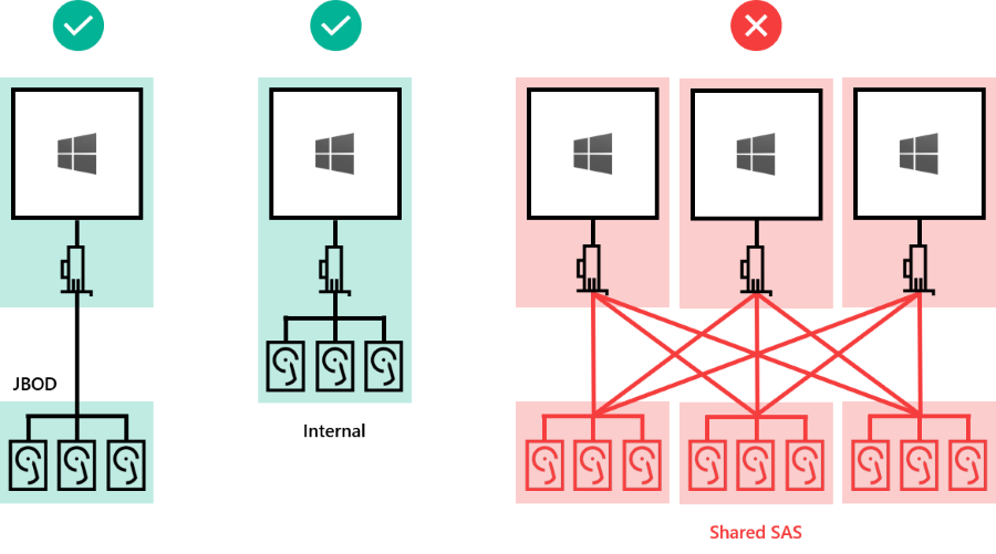
Storage spaces direct (S2D) wants all the hosts to be similar, in that they have the same type and amount of disks, and I would also recommend the same CPU. The storage CPU load for each volume takes place on the host that owns that volume. I think having mismatched CPU's would probably affect the performance of that volume significantly. You also need multiple RDMA capable 10GB interfaces.

I have 3 hosts that look like this:-

HP DL380 Gen9
Dual E5-2640v5
256GB RAM
2 x Chelsio 10GB network cards
1 x HP P440 Raid controller.
2 x HP H240 HBA
16 x 480GB Intel enterprise SSD's
2 x SATA drives

Switching, I have a pair of Arista switches for the 10GB and some Aruba affair for the 1GB.

I should also point out that this is currently POC kit bought specifically for this and that once I am happy with it all we will likely use this same kit in our public cloud environment.

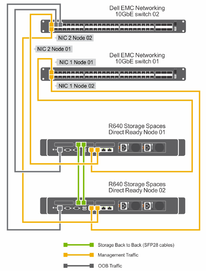
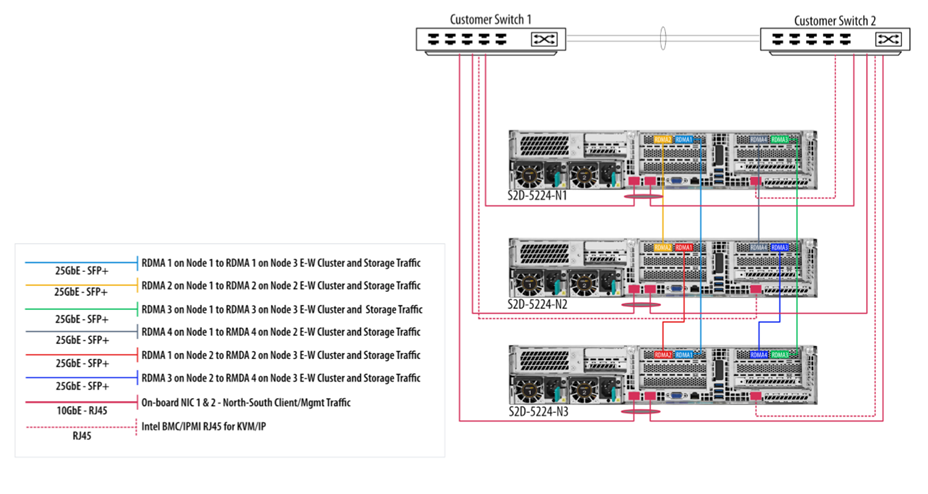
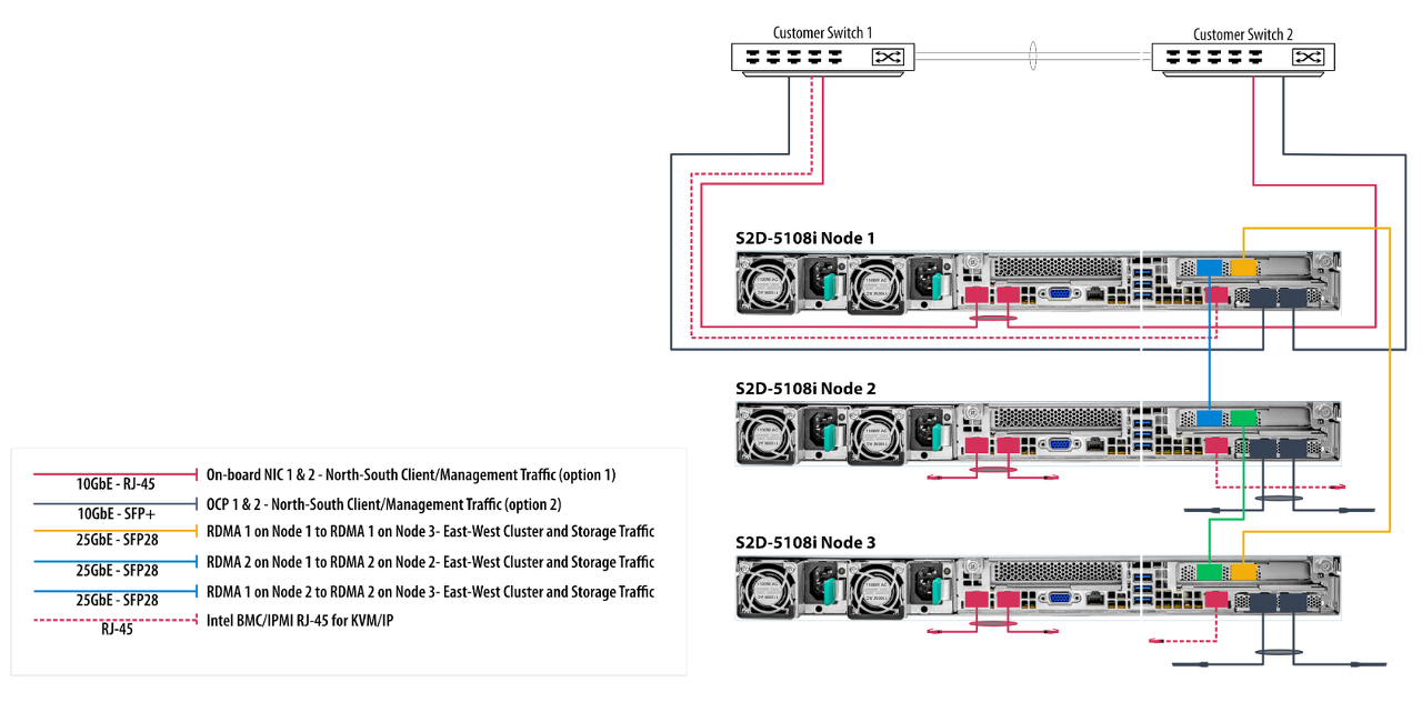
The physical architecture is your standard cluster with redundant networks. I'm not going to document that but here.

Installation

First thing is to install Windows Server 2016 and all its updates. It also a good idea to properly name all your NIC interfaces as that will make it a lot easier to identify them later on.

Next, we need to install all the windows features required for S2D. This script should get them all in one go

Install-WindowsFeature -Name "Data-Center-Bridging","Failover-Clustering","Hyper-V","RSAT-Clustering-PowerShell","RSAT-Clustering-Mgmt","Hyper-V-PowerShell" -Restart  

This will likely need a reboot.

Once all this is done we can start putting together the required networking. This requires a little thought.
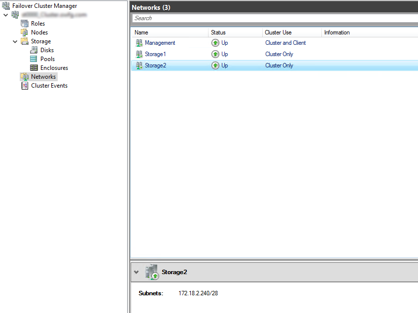
Network

S2D uses switch embedded teaming (SET). This is not the same as the switch teaming you may have used before. It has no GUI and can only be done from PowerShell. You need to be using SET in order to use the RDMA feature of your network cards. Switch embedded teaming also has support for some other features not available in standard NIC teaming. Microsoft has written a lovely little guide for you here. I warn you it's pretty long...

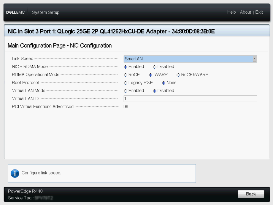
Depending on your choice of NIC you may also need to do some additional switch config to get RDMA to work. I chose a Chelsio card that has an RDMA implantation called iWarp, that doesn't need any specific switch config. It seemed like the easiest thing to do.

Now we start. The first thing we need to do is to create a QoS policy and give SMB high priority and a guaranteed allocation. You don't need to do this but it makes sense, especially in a hyper-converged environment where there may be resource contention.

You need to execute the following commands on all the servers that you plan to be in your cluster.

New-NetQosPolicy "SMB" -NetDirectPortMatchCondition 445 -PriorityValue8021Action 3

Enable-NetQosFlowControl -Priority 3

Disable-NetQosFlowControl -Priority 0,1,2,4,5,6,7

New-NetQosTrafficClass "SMB" –Priority 3 –BandwidthPercentage 30 –Algorithm ETS

The last line of that code essentially reserves 30% of the network specifically for S2D, which is what we want.

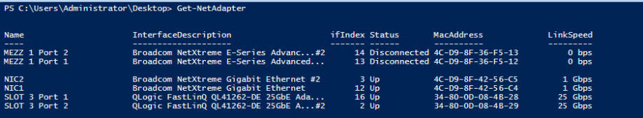
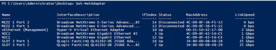
Now we need to enable the QoS policy on the relevant interfaces. To get a list of the NIC's run the following

Get-NetAdapter | FT Name, InterfaceDescription, Status, LinkSpeed

Which will give you something like this

  Name                  InterfaceDescription                         Status   LinkSpeed
----                  --------------------                         ------       -------
StorageNIC1           Chelsio Network Adapter #4                   Up           10 Gbps  
Ethernet 3            Chelsio Network Adapter #3                   Disconnected 0 bps    
VLAN 10               Microsoft Network Adapter Multiplexor Driver Up           2 Gbps   
StorageNIC2           Chelsio Network Adapter #2                   Up           10 Gbps  
Ethernet              Chelsio Network Adapter                      Disconnected 0 bps    
Embedded LOM 1 Port 4 HP Ethernet 1Gb 4-port 331i Adapter #4       Disconnected 0 bps    
Embedded LOM 1 Port 3 HP Ethernet 1Gb 4-port 331i Adapter #3       Disconnected 0 bps    
Embedded LOM 1 Port 2 HP Ethernet 1Gb 4-port 331i Adapter #2       Up           1 Gbps   
Embedded LOM 1 Port 1 HP Ethernet 1Gb 4-port 331i Adapter          Up           1 Gbps  

I need the policy on my 10GB storage interfaces, which I helpfully labeled during the hardware install. The other 2 are for migration and client traffic so won't be used for storage traffic and therefor don't need the policy.

Enable-NetAdapterQos –Name "StorageNIC1","StorageNIC2"

That bit is not done. We need to create the virtual switch and sort out the teaming (SET)

Again we will need the name of the storage NICs, which you should have from the previous step.

So we create the vSwitch

New-VMSwitch –Name vStorage –NetAdapterName "StorageNIC1", "StorageNIC2" –EnableEmbeddedTeaming $true

And now for the bit that I struggled to grasp for a while. Creating the vSwitch creates a single interface that has the name of the switch. This seems like it would be the vNIC you should be using. However, in testing, I have discovered that if I assign an IP to this vNIC and simulate failure in the physical NICS it does fail-over, but it takes a long time. Too long. So what we do is create 2 additional vNICs connected to the vSwitch, and map them to the physical. Essentially creating 2 diverse paths and allowing us to use the full 20GB of the network.

If one of the NIC's fails they IP will still fail-over to the other, and it still takes a long time, however, it doesn't matter due to the second path.

Add-VMNetworkAdapter –SwitchName vStorage –Name SMB_1 –managementOS
Add-VMNetworkAdapter –SwitchName vStorage –Name SMB_2 –managementOS
Set-VMNetworkAdapterVlan -VMNetworkAdapterName "SMB_1" -VlanId 48 -Access -ManagementOS
Set-VMNetworkAdapterVlan -VMNetworkAdapterName "SMB_2" -VlanId 48 -Access -ManagementOS

Once this is done restart the vNICs

Restart-NetAdapter "vEthernet (SMB_1)"
Restart-NetAdapter "vEthernet (SMB_2)"

And then we enable RDMA on these vNICS

Enable-NetAdapterRDMA "vEthernet (SMB_1)", "vEthernet (SMB_2)"

Finally, we assign them to a physical interface.

Set-VMNetworkAdapterTeamMapping -VMNetworkAdapterName "SMB_1" –ManagementOS –PhysicalNetAdapterName "StorageNIC1"
Set-VMNetworkAdapterTeamMapping -VMNetworkAdapterName "SMB_2" –ManagementOS –PhysicalNetAdapterName StorageNIC2"

Now we check if the relevant interfaces are set up correctly.

Get-SmbClientNetworkInterface

You should see this

Interface Index RSS Capable RDMA Capable Speed    IpAddresses   Friendly Name                                      
--------------- ----------- ------------ -----    -----------   -----------                                    

49              True        True         20 Gbps  {fe80::1964:a4a2:5f4d:b7e8,10.2.120.21}     vEthernet (SMB_1)                                  
53              True        True         20 Gbps  {fe80::ac59:19fa:1685:1247,10.2.121.21}     vEthernet (SMB_2)       

RDMA is enabled.

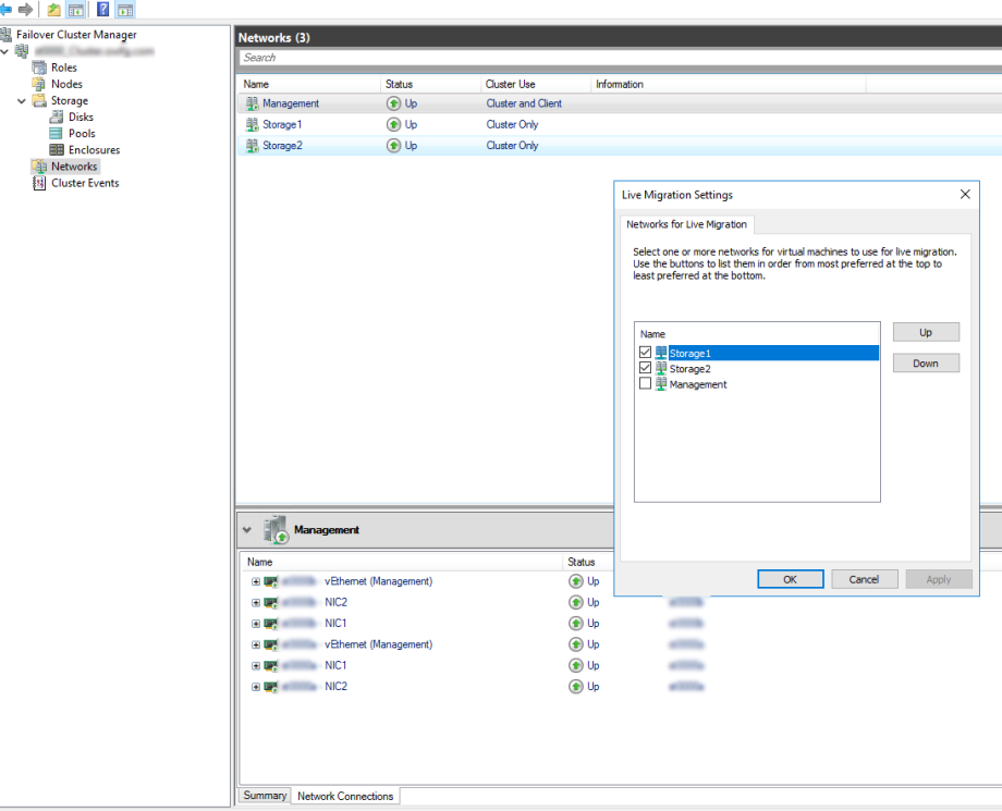
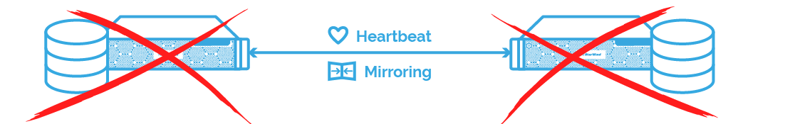
At this point, it's a good idea to assign your IP address and do some testing. Make sure things fail-over as expected, at the very least to make yourself familiar with what to expect from this sort of configuration.

That's the networking done, now we move onto creating the cluster.

Cluster

The first thing to do is some cluster tests to make sure we haven't forgotten anything.

Test-Cluster –Node MachineName1, MachineName2, MachineName3, –Include "Storage Spaces Direct", "Inventory", "Network", "System Configuration"

For me this threw up an error. The vNIC that is created when we created the switch I mentioned earlier has no IP config assigned. You can ignore this or better still disable that interface. Once I did this the cluster validation came back as OK. So now we can move on and create the cluster.

New-Cluster -Name clustername -StaticAddress x.x.x.x –Node MachineName1, MachineName2, MachineName3, –NoStorage

You need the -NoStrage argument as otherwise it will capture all the disks and add them to the cluster. You don't want this yet.

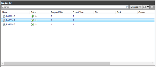
Now depending how many nodes you have you may want to create a witness for the cluster, in the form of another server of a quorum. I assume you know how to so that and will if needed.
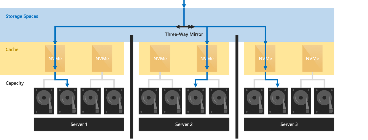
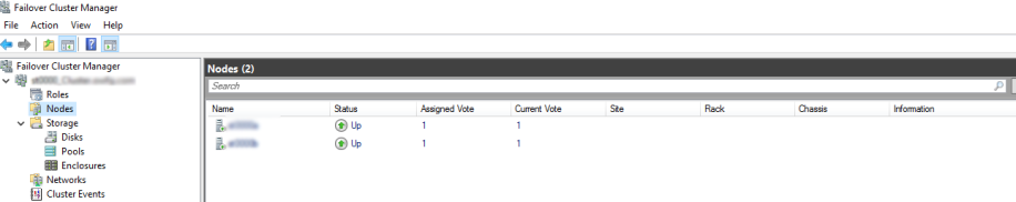
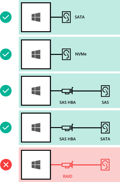
S2D

Now we get to the part where we enable storage spaces direct and add the S2D compatible disks to the storage pool. According to Microsoft S2D wants "Clean" disks. No existing partition data on them and give you this script to clean your disks.

icm (Get-Cluster -Name <cluster or node name> | Get-ClusterNode) {

Update-StorageProviderCache

Get-StoragePool | ? IsPrimordial -eq $false | Set-StoragePool -IsReadOnly:$false -
ErrorAction SilentlyContinue

Get-StoragePool | ? IsPrimordial -eq $false | Get-VirtualDisk | Remove-VirtualDisk -
Confirm:$false -ErrorAction SilentlyContinue

Get-StoragePool | ? IsPrimordial -eq $false | Remove-StoragePool -Confirm:$false -
ErrorAction SilentlyContinue

Get-PhysicalDisk | Reset-PhysicalDisk -ErrorAction SilentlyContinue

Get-Disk | ? Number -ne $null | ? IsBoot -ne $true | ? IsSystem -ne $true | ? 
PartitionStyle -ne RAW | % {

$_ | Set-Disk -isoffline:$false

$_ | Set-Disk -isreadonly:$false

$_ | Clear-Disk -RemoveData -RemoveOEM -Confirm:$false

$_ | Set-Disk -isreadonly:$true

$_ | Set-Disk -isoffline:$true

}

Get-Disk |? Number -ne $null |? IsBoot -ne $true |? IsSystem -ne $true |? PartitionStyle -eq RAW | Group -NoElement -Property FriendlyName

} | Sort -Property PsComputerName,Count

Out of curiosity I tried to enable S2D with out doing this and unsurprisingly it failed. Don't skip this step, but also be aware this will flatten all the disks in the host. If you want to be more precise you may want to try using DiskPart.

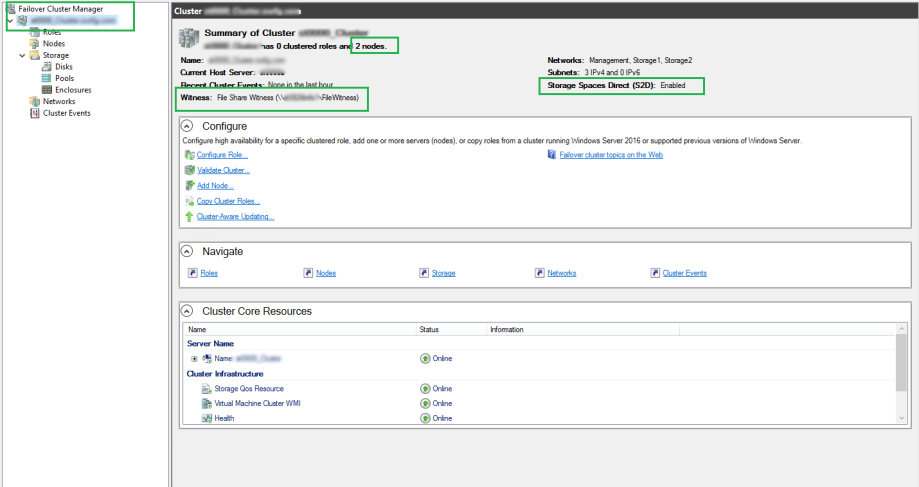
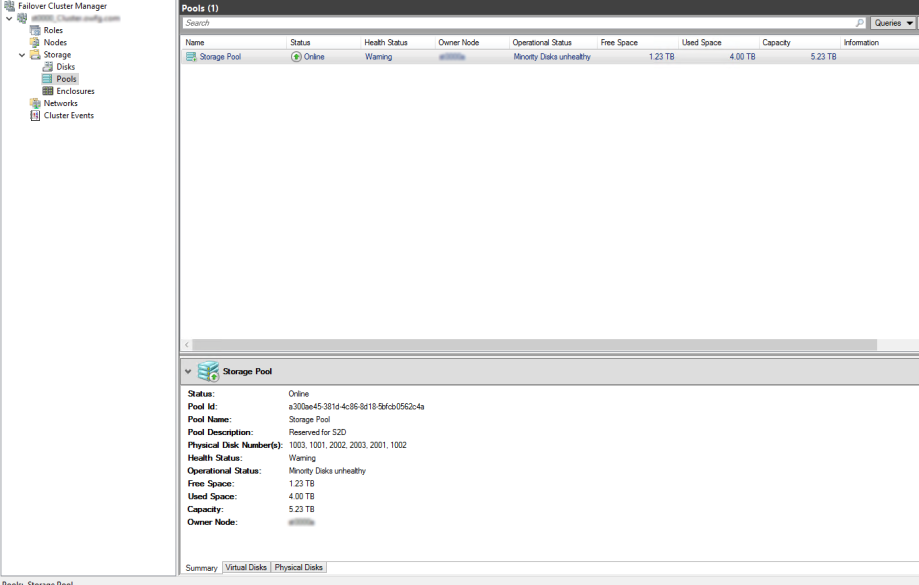
Finally we enable storage spaces direct.

Enable-ClusterStorageSpacesDirect –CimSession <ClusterName>

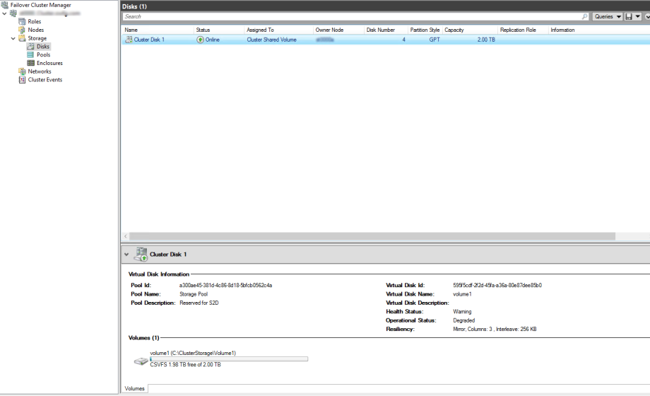
And we are done. You can now create vdisks and Volumes from the GUI if you wish but I would recommend that you use New-Volume in PowerShell as there are some specifics you may want to add to you new disks.

I will write another guide on that next I think.

If you have any feedback on this please comment bellow.

728x90
728x90

This blog post will focus on deploying Storage Spaces Direct (S2D) with Windows Server 2016 (steps with Server 2019 should be very-very similar, if not exact…) in a RoBo (Remote Office Branch Office) configuration with Dell Ready Nodes (S2DRN) leveraging RDMA (Remote Direct Memory Access). Now that is a mouthful, so let’s focus on what is Storage Spaces Direct first.

What is Storage Spaces Direct? With Server 2016, Microsoft introduced Storage Spaces Direct (S2D) with the release of Server 2016. S2D allows you to take industry-standard servers and leverage the internal local drives within the nodes and create a highly-available, highly-scalable software defined storage. Using hyper-converged or converged architecture, you are able to quickly deploy, scale storage, while implementing features such as storage tiers, caching, all while taking advantage of RDMA networking.

What is RDMA? Remote Direct Memory Access, or in short, RDMA, is an enterprise networking technology that allows you to exchange data through memory, without consuming the CPU or Operating System kernel. RDMA allows your applications to have high IOPS and with very low latency, while leveraging either RoCe (RDMA over Converged Ethernet) or iWARP (Internet Wide Area RDMA Protocol).

Note: the steps below focus on a single node of a 2-node cluster. All the steps below need to be executed on the secondary node.


Network Connectivity

Before we begin implementing, deploying and configuring we need to plan out the networking connectivity design. However before we do that, we need to understand what our design will look like. Below is a high-level diagram that illustrates the network connectivity for the host management and VM traffic, and the RDMA (Storage) traffic.


Network Configuration

Next we should map out our IP configuration. With this 2-node deployment we know we need the following network adapters and the following IPs.

Traffic Class Purpose Minimum IPs required VLAN ID Tagged/Untagged IP Address Space VLAN IP Address
Out of Band (iDRAC) Remote Management 2   Untagged /29  
Management (Host) Management of Cluster and Cluster Nodes 3   Tagged/Untagged /29  
Storage 01 SMB Traffic 2   Tagged/Untagged /29  
Storage 02 SMB Traffic 2   Tagged/Untagged /29  

Now that we have defined our networking configuration, we can move forward with booting the nodes, and making some necessary changes to the BIOS.


BIOS Configuration

Launch the node, and log into the BIOS (usually F2 at the Dell prompt)… Next go to the Device settings and let’s configure the RDMA/QLogic adapters.

Your configuration should look similar to this. In my instance, I am leveraging iWARP and not RoCE. By default, the adapters will allow for both modes, but we want to force iWARP only.

Disable Virtualization Mode

Disable DCBX (Data Center Bridging)

  • Link Speed: SmartAN
  • NIC + RDMA Mode: Enabled
  • RDMA Operation Mode: iWARP
  • Virtual LAN ID: 1 (which is default)

Remember, this needs to be done to both RDMA adapters!!! Once the settings have been applied, and saved, go ahead and reboot the node. Remember to do the second node too!


Install & Update Operating System

Next, we now need to install the Operating System. As best practice, once the OS is installed, update the OS and update all network drivers.


Validate & Rename Network Adapters

Also, it is a good idea to rename the Network adapters. Before we do that, let’s just confirm the adapters are there and look right.

1
Get-NetAdapter


Install Windows Features & Roles

Once the OS has been installed, and patched. Next we now need to install the necessary roles and features, ie. Hyper-V, Failover Manager, etc.

1
Install-WindowsFeature -Name Hyper-V, Failover-Clustering -IncludeAllSubFeature -IncludeManagementTools -Verbose -Restart

Configure Host Network

Now we need to configure the host management network. In this step we will create a SET switch (Switch Embedded Teaming). This switch will not only team the two network (host) adapters but at the same time a SET switch will be created that will be leveraged by the guest VMs via Hyper-V.

1
New-VMSwitch -Name S2DSwitch -AllowManagementOS 0 -NetAdapterName 'NIC1','NIC2' -MinimumBandwidthMode Weight -Verbose

Within this code, note, NIC1 and NIC2 are the host management adapters that were renamed to make life easier.

Now we need to create and configure the host management adapter. We will do this by executing the following cmdlet. Please note, in my environment, the Host Management network is untagged.

1
Add-VMNetworkAdapter -ManagementOS -Name 'Management' -SwitchName S2DSwitch -Passthru | Set-VMNetworkAdapterVlan -Untagged –Verbose

Once we execute this command, and run the Get-NetAdapter cmdlet, we can now see we have an additional network adapter.

In the event you need to tag your Management adapters you can use the following cmdlet below as reference.

1
2
Set-NetAdapterAdvancedProperty -Name 'SLOT 3 PORT 1' -DisplayName 'VLAN ID' -DisplayValue 103 -Verbose
Set-NetAdapterAdvancedProperty -Name 'SLOT 3 PORT 2' -DisplayName 'VLAN ID' -DisplayValue 104 -Verbose

Great, now we can add the nodes to the domain, and set the Management network adapters with static IPs.


Create the Cluster, Configure Witness, Enable Storage Spaces Direct

Now that are nodes are domain joined, and static IPs have been applied to the host management network, we can now begin creating the cluster.

In the code below, I am going to create the cluster; add the two nodes to the cluster; provision the Quorum witness (file witness) and enable Storage Spaces Direct on the cluster.

1
2
3
4
5
6
$cluster="Cluster_Name"
New-Cluster -name $cluster -Node "node01", "node02" -StaticAddress "IP Address" -NoStorage -Verbose
#assign cluster quorum
Set-ClusterQuorum -Cluster $cluster -FileShareWitness "\\server\filewitness\UNCPatch"
#enable storage spaces direct
Enable-ClusterS2D -Verbose

Once we have executed the commands above, if we launch Failover Manager, we can now see the created Cluster, with the 2 nodes, and Storage Spaces Direct enabled.


If we go into the Pool, we can also now see our Software Defined Storage Pool. We now can create volumes off of this pool.

If we go into the Enclosures, we can now also see all the disks available within the nodes and all disks that are members of the Storage Pool.

Great, now we need to do some configuration on the RDMA Adapters… Also to note, in this scenario I have leveraged a file share witness for the cluster. I would highly recommend considering or using Azure Cloud Witness. The egress traffic is next to 0, and you can connect several clusters to the storage account. For more information, see the following blog post(s): HERE.


Change RDMA mode to iWARP on QLogic Adapters

Again, remember which RDMA adapter is which. As mentioned previously, I renamed all of the network adapters to keep things simple and easy to remember.

1
2
Set-NetAdapterAdvancedProperty -Name 'SLOT 3 PORT 1' -DisplayName 'RDMA Mode' -DisplayValue 'iWarp'
Set-NetAdapterAdvancedProperty -Name 'SLOT 3 PORT 2' -DisplayName 'RDMA Mode' -DisplayValue 'iWarp'

Now we can leverage the QLogic adapters with RDMA via iWARP for our Storage traffic.


Create Cluster Shared Volumes (CSV)

Now that our cluster is created, nodes have been added, RDMA is configured, we can now create a CSV that will be leveraged by the VMs as their data store. We will do this by creating the CSV with the following cmdlet.

1
New-Volume -StoragePoolFriendlyName "Storage Pool" -FriendlyName "Volume01" -FileSystem CSVFS_ReFS -size 2TB

Now I elected to keep the CSV small with a 2TB volume, however I did have another 3TB to work with.


Update Live Migration

We are almost there, we now need to update the Live Migration network. This will ensure we make use of the RDMA network and not the Management network. We will do this via Failover Manager console.

Also a good idea to rename the networks. As you can see, I have renamed my storage networks to Storage1 and Storage2, and the host management network to Management.

Go to the Failover Manager Console >> Right Click Networks >> Select Live Migration Settings >> deselect the Management network.

\

You may have also noticed, I have configured the networks and their cluster use. Storage networks will be only available for the cluster, and the Management network will be available for both the cluster and client (guest VMs).


Next steps

We have now successfully created a Storage Spaces Direct cluster, leveraging RDMA networking and using the iWARP protocol. We now also created a SET switch that can be leveraged by our VMs as their network adapter. We have now also created a Storage Pool, with a volume dedicated for our VM disks leveraging the Cluster Shared Volume.

Next steps is now to create a VM and leveraging Storage Spaces Direct!

728x90
728x90

This article describes minimum hardware requirements for Storage Spaces Direct. For hardware requirements on Azure Stack HCI, our operating system designed for hyperconverged deployments with a connection to the cloud, see Before you deploy Azure Stack HCI: Determine hardware requirements.

For production, Microsoft recommends purchasing a validated hardware/software solution from our partners, which include deployment tools and procedures. These solutions are designed, assembled, and validated against our reference architecture to ensure compatibility and reliability, so you get up and running quickly. For hardware solutions, visit the Azure Stack HCI solutions website.

 Tip

Want to evaluate Storage Spaces Direct but don't have hardware? Use Hyper-V or Azure virtual machines as described in Using Storage Spaces Direct in guest virtual machine clusters.

Base requirements

Systems, components, devices, and drivers must be certified for the operating system you’re using in the Windows Server Catalog. In addition, we recommend that servers and network adapters have the Software-Defined Data Center (SDDC) Standard and/or Software-Defined Data Center (SDDC) Premium additional qualifications (AQs), as pictured below. There are over 1,000 components with the SDDC AQs.

The fully configured cluster (servers, networking, and storage) must pass all cluster validation tests per the wizard in Failover Cluster Manager or with the Test-Cluster cmdlet in PowerShell.

In addition, the following requirements apply:

Servers

  • Minimum of 2 servers, maximum of 16 servers
  • Recommended that all servers be the same manufacturer and model

CPU

  • Intel Nehalem or later compatible processor; or
  • AMD EPYC or later compatible processor

Memory

  • Memory for Windows Server, VMs, and other apps or workloads; plus
  • 4 GB of RAM per terabyte (TB) of cache drive capacity on each server, for Storage Spaces Direct metadata

Boot

  • Any boot device supported by Windows Server, which now includes SATADOM
  • RAID 1 mirror is not required, but is supported for boot
  • Recommended: 200 GB minimum size

Networking

Storage Spaces Direct requires a reliable high bandwidth, low latency network connection between each node.

Minimum interconnect for small scale 2-3 node

  • 10 Gbps network interface card (NIC), or faster
  • Two or more network connections from each node recommended for redundancy and performance

Recommended interconnect for high performance, at scale, or deployments of 4+

  • NICs that are remote-direct memory access (RDMA) capable, iWARP (recommended) or RoCE
  • Two or more network connections from each node recommended for redundancy and performance
  • 25 Gbps NIC or faster

Switched or switchless node interconnects

  • Switched: Network switches must be properly configured to handle the bandwidth and networking type. If using RDMA that implements the RoCE protocol, network device and switch configuration is even more important.
  • Switchless: Nodes can be interconnected using direct connections, avoiding using a switch. It's required that every node has a direct connection with every other node of the cluster.

Drives

Storage Spaces Direct works with direct-attached SATA, SAS, NVMe, or persistent memory (PMem) drives that are physically attached to just one server each. For more help choosing drives, see the Choosing drives and Understand and deploy persistent memory articles.

  • SATA, SAS, persistent memory, and NVMe (M.2, U.2, and Add-In-Card) drives are all supported
  • 512n, 512e, and 4K native drives are all supported
  • Solid-state drives must provide power-loss protection
  • Same number and types of drives in every server – see Drive symmetry considerations
  • Cache devices must be 32 GB or larger
  • Persistent memory devices are used in block storage mode
  • When using persistent memory devices as cache devices, you must use NVMe or SSD capacity devices (you can't use HDDs)
  • If you're using HDDs to provide storage capacity, you must use storage bus caching. Storage bus caching isn't required when using all-flash deployments
  • NVMe driver is the Microsoft-provided one included in Windows (stornvme.sys)
  • Recommended: Number of capacity drives is a whole multiple of the number of cache drives
  • Recommended: Cache drives should have high write endurance: at least 3 drive-writes-per-day (DWPD) or at least 4 terabytes written (TBW) per day – see Understanding drive writes per day (DWPD), terabytes written (TBW), and the minimum recommended for Storage Spaces Direct

 Note

When using all flash drives for storage capacity, the benefits of storage pool caching will be limited. Learn more about the storage pool cache.

Here's how drives can be connected for Storage Spaces Direct:

  • Direct-attached SATA drives
  • Direct-attached NVMe drives
  • SAS host-bus adapter (HBA) with SAS drives
  • SAS host-bus adapter (HBA) with SATA drives
  • NOT SUPPORTED: RAID controller cards or SAN (Fibre Channel, iSCSI, FCoE) storage. Host-bus adapter (HBA) cards must implement simple pass-through mode for any storage devices used for Storage Spaces Direct.

Drives can be internal to the server, or in an external enclosure that is connected to just one server. SCSI Enclosure Services (SES) is required for slot mapping and identification. Each external enclosure must present a unique identifier (Unique ID).

  • Drives internal to the server
  • Drives in an external enclosure ("JBOD") connected to one server
  • NOT SUPPORTED: Shared SAS enclosures connected to multiple servers or any form of multi-path IO (MPIO) where drives are accessible by multiple paths.

Minimum number of drives (excludes boot drive)

The minimum number of capacity drives you require varies with your deployment scenario. If you're planning to use the storage pool cache, there must be at least 2 cache devices per server.

You can deploy Storage Spaces Direct on a cluster of physical servers or on virtual machine (VM) guest clusters. You can configure your Storage Spaces Direct design for performance, capacity, or balanced scenarios based on the selection of physical or virtual storage devices. Virtualized deployments take advantage of the private or public cloud's underlying storage performance and resilience. Storage Spaces Direct deployed on VM guest clusters allows you to use high availability solutions within virtual environment.

The following sections describe the minimum drive requirements for physical and virtual deployments.

Physical deployments

This table shows the minimum number of capacity drives by type for hardware deployments such as Azure Stack HCI version 21H2 or later, and Windows Server.

Drive type present (capacity only)Minimum drives required (Windows Server)Minimum drives required (Azure Stack HCI)
All persistent memory (same model) 4 persistent memory 2 persistent memory
All NVMe (same model) 4 NVMe 2 NVMe
All SSD (same model) 4 SSD 2 SSD

If you're using the storage pool cache, there must be at least 2 more drives configured for the cache. The table shows the minimum numbers of drives required for both Windows Server and Azure Stack HCI deployments using 2 or more nodes.

Drive type presentMinimum drives required
Persistent memory + NVMe or SSD 2 persistent memory + 4 NVMe or SSD
NVMe + SSD 2 NVMe + 4 SSD
NVMe + HDD 2 NVMe + 4 HDD
SSD + HDD 2 SSD + 4 HDD

 Important

The storage pool cache cannot be used with Azure Stack HCI in a single node deployment.

Virtual deployment

This table shows the minimum number of drives by type for virtual deployments such as Windows Server guest VMs or Windows Server Azure Edition.

Drive type present (capacity only)Minimum drives required
Virtual Hard Disk 2

 Tip

To boost the performance for guest VMs when running on Azure Stack HCI or Windows Server, consider using the CSV in-memory read cache to cache unbuffered read operations.

If you're using Storage Spaces Direct in a virtual environment, you must consider:

  • Virtual disks aren't susceptible to failures like physical drives are, however you're dependent on the performance and reliability of the public or private cloud
  • It's recommended to use a single tier of low latency / high performance storage
  • Virtual disks must be used for capacity only

Learn more about deploying Storage Spaces Direct using virtual machines and virtualized storage.

Maximum capacity

MaximumsWindows Server 2019 or laterWindows Server 2016
Raw capacity per server 400 TB 100 TB
Pool capacity 4 PB (4,000 TB) 1 PB
728x90
728x90

This topic describes how to add servers or drives to Storage Spaces Direct.

Adding servers

Adding servers, often called scaling out, adds storage capacity and can improve storage performance and unlock better storage efficiency. If your deployment is hyper-converged, adding servers also provides more compute resources for your workload.

Typical deployments are simple to scale out by adding servers. There are just two steps:

  1. Run the cluster validation wizard using the Failover Cluster snap-in or with the Test-Cluster cmdlet in PowerShell (run as Administrator). Include the new server <NewNode> you wish to add.
    Test-Cluster -Node <Node>, <Node>, <Node>, <NewNode> -Include "Storage Spaces Direct", Inventory, Network, "System Configuration"
    
    This confirms that the new server is running Windows Server 2016 Datacenter Edition, has joined the same Active Directory Domain Services domain as the existing servers, has all the required roles and features, and has networking properly configured.
  2.  Important
  3. If you are re-using drives that contain old data or metadata you no longer need, clear them using Disk Management or the Reset-PhysicalDisk cmdlet. If old data or metadata is detected, the drives aren't pooled.
  4. PowerShellCopy
  5. Run the following cmdlet on the cluster to finish adding the server:
Copy
Add-ClusterNode -Name NewNode

 Note

Automatic pooling depends on you having only one pool. If you've circumvented the standard configuration to create multiple pools, you will need to add new drives to your preferred pool yourself using Add-PhysicalDisk.

From 2 to 3 servers: unlocking three-way mirroring

With two servers, you can only create two-way mirrored volumes (compare with distributed RAID-1). With three servers, you can create three-way mirrored volumes for better fault tolerance. We recommend using three-way mirroring whenever possible.

Two-way mirrored volumes cannot be upgraded in-place to three-way mirroring. Instead, you can create a new volume and migrate (copy, such as by using Storage Replica) your data to it, and then remove the old volume.

To begin creating three-way mirrored volumes, you have several good options. You can use whichever you prefer.

Option 1

Specify PhysicalDiskRedundancy = 2 on each new volume upon creation.

PowerShellCopy
New-Volume -FriendlyName <Name> -FileSystem CSVFS_ReFS -StoragePoolFriendlyName S2D* -Size <Size> -PhysicalDiskRedundancy 2

Option 2

Instead, you can set PhysicalDiskRedundancyDefault = 2 on the pool's ResiliencySetting object named Mirror. Then, any new mirrored volumes will automatically use three-way mirroring even if you don't specify it.

PowerShellCopy
Get-StoragePool S2D* | Get-ResiliencySetting -Name Mirror | Set-ResiliencySetting -PhysicalDiskRedundancyDefault 2

New-Volume -FriendlyName <Name> -FileSystem CSVFS_ReFS -StoragePoolFriendlyName S2D* -Size <Size>

Option 3

Set PhysicalDiskRedundancy = 2 on the StorageTier template called Capacity, and then create volumes by referencing the tier.

PowerShellCopy
Set-StorageTier -FriendlyName Capacity -PhysicalDiskRedundancy 2

New-Volume -FriendlyName <Name> -FileSystem CSVFS_ReFS -StoragePoolFriendlyName S2D* -StorageTierFriendlyNames Capacity -StorageTierSizes <Size>

From 3 to 4 servers: unlocking dual parity

With four servers, you can use dual parity, also commonly called erasure coding (compare to distributed RAID-6). This provides the same fault tolerance as three-way mirroring, but with better storage efficiency. To learn more, see Fault tolerance and storage efficiency.

If you're coming from a smaller deployment, you have several good options to begin creating dual parity volumes. You can use whichever you prefer.

Option 1

Specify PhysicalDiskRedundancy = 2 and ResiliencySettingName = Parity on each new volume upon creation.

PowerShellCopy
New-Volume -FriendlyName <Name> -FileSystem CSVFS_ReFS -StoragePoolFriendlyName S2D* -Size <Size> -PhysicalDiskRedundancy 2 -ResiliencySettingName Parity

Option 2

Set PhysicalDiskRedundancy = 2 on the pool's ResiliencySetting object named Parity. Then, any new parity volumes will automatically use dual parity even if you don't specify it

PowerShellCopy
Get-StoragePool S2D* | Get-ResiliencySetting -Name Parity | Set-ResiliencySetting -PhysicalDiskRedundancyDefault 2

New-Volume -FriendlyName <Name> -FileSystem CSVFS_ReFS -StoragePoolFriendlyName S2D* -Size <Size> -ResiliencySettingName Parity

With four servers, you can also begin using mirror-accelerated parity, where an individual volume is part mirror and part parity.

For this, you will need to update your StorageTier templates to have both Performance and Capacity tiers, as they would be created if you had first run Enable-ClusterS2D at four servers. Specifically, both tiers should have the MediaType of your capacity devices (such as SSD or HDD) and PhysicalDiskRedundancy = 2. The Performance tier should be ResiliencySettingName = Mirror, and the Capacity tier should be ResiliencySettingName = Parity.

Option 3

You may find it easiest to simply remove the existing tier template and create the two new ones. This will not affect any pre-existing volumes which were created by referring the tier template: it's just a template.

PowerShellCopy
Remove-StorageTier -FriendlyName Capacity

New-StorageTier -StoragePoolFriendlyName S2D* -MediaType HDD -PhysicalDiskRedundancy 2 -ResiliencySettingName Mirror -FriendlyName Performance
New-StorageTier -StoragePoolFriendlyName S2D* -MediaType HDD -PhysicalDiskRedundancy 2 -ResiliencySettingName Parity -FriendlyName Capacity

That's it! You are now ready to create mirror-accelerated parity volumes by referencing these tier templates.

Example

PowerShellCopy
New-Volume -FriendlyName "Sir-Mix-A-Lot" -FileSystem CSVFS_ReFS -StoragePoolFriendlyName S2D* -StorageTierFriendlyNames Performance, Capacity -StorageTierSizes <Size, Size>

Beyond 4 servers: greater parity efficiency

As you scale beyond four servers, new volumes can benefit from ever-greater parity encoding efficiency. For example, between six and seven servers, efficiency improves from 50.0% to 66.7% as it becomes possible to use Reed-Solomon 4+2 (rather than 2+2). There are no steps you need to take to begin enjoying this new efficiency; the best possible encoding is determined automatically each time you create a volume.

However, any pre-existing volumes will not be "converted" to the new, wider encoding. One good reason is that to do so would require a massive calculation affecting literally every single bit in the entire deployment. If you would like pre-existing data to become encoded at the higher efficiency, you can migrate it to new volume(s).

For more details, see Fault tolerance and storage efficiency.

Adding servers when using chassis or rack fault tolerance

If your deployment uses chassis or rack fault tolerance, you must specify the chassis or rack of new servers before adding them to the cluster. This tells Storage Spaces Direct how best to distribute data to maximize fault tolerance.

  1. Create a temporary fault domain for the node by opening an elevated PowerShell session and then using the following command, where <NewNode> is the name of the new cluster node:
    New-ClusterFaultDomain -Type Node -Name <NewNode>
    
  2. PowerShellCopy
  3. Move this temporary fault-domain into the chassis or rack where the new server is located in the real world, as specified by <ParentName>:
    Set-ClusterFaultDomain -Name <NewNode> -Parent <ParentName>
    
    For more information, see Fault domain awareness in Windows Server 2016.
  4. PowerShellCopy
  5. Add the server to the cluster as described in Adding servers. When the new server joins the cluster, it's automatically associated (using its name) with the placeholder fault domain.

Adding drives

Adding drives, also known as scaling up, adds storage capacity and can improve performance. If you have available slots, you can add drives to each server to expand your storage capacity without adding servers. You can add cache drives or capacity drives independently at any time.

 Important

We strongly recommend that all servers have identical storage configurations.

To scale up, connect the drives and verify that Windows discovers them. They should appear in the output of the Get-PhysicalDisk cmdlet in PowerShell with their CanPool property set to True. If they show as CanPool = False, you can see why by checking their CannotPoolReason property.

PowerShellCopy
Get-PhysicalDisk | Select SerialNumber, CanPool, CannotPoolReason

Within a short time, eligible drives will automatically be claimed by Storage Spaces Direct, added to the storage pool, and volumes will automatically be redistributed evenly across all the drives. At this point, you're finished and ready to extend your volumes or create new ones.

If the drives don't appear, manually scan for hardware changes. This can be done using Device Manager, under the Action menu. If they contain old data or metadata, consider reformatting them. This can be done using Disk Management or with the Reset-PhysicalDisk cmdlet.

 Note

Automatic pooling depends on you having only one pool. If you've circumvented the standard configuration to create multiple pools, you will need to add new drives to your preferred pool yourself using Add-PhysicalDisk.

Optimizing drive usage after adding drives or servers

Over time, as drives are added or removed, the distribution of data among the drives in the pool can become uneven. In some cases, this can result in certain drives becoming full while other drives in pool have much lower consumption.

To help keep drive allocation even across the pool, Storage Spaces Direct automatically optimizes drive usage after you add drives or servers to the pool (this is a manual process for Storage Spaces systems that use Shared SAS enclosures). Optimization starts 15 minutes after you add a new drive to the pool. Pool optimization runs as a low-priority background operation, so it can take hours or days to complete, especially if you're using large hard drives.

Optimization uses two jobs - one called Optimize and one called Rebalance - and you can monitor their progress with the following command:

PowerShellCopy
Get-StorageJob

You can manually optimize a storage pool with the Optimize-StoragePool cmdlet. Here's an example:

PowerShellCopy
Get-StoragePool <PoolName> | Optimize-StoragePool
728x90
728x90

When taking an S2D server offline for patching or other reasons, it is not only taking away the compute and memory for that server but also a portion of the storage pool. Care must be taken to keep your data safe and ensure quick resumption of production-level readiness to your cluster.


Visit Microsoft for the full description and latest information: https://docs.microsoft.com/en-us/windows-server/storage/storage-spaces/maintain-servers


Key Steps to reboot servers:

1. Open PowerShell as Admin.


2. Check to make sure the virtual disks are healthy by running Get-VirtualDisk.


3. Run Suspend-ClusterNode -Drain to move the VMs to another node.


4. Run to cleanly put the storage into maintenance mode. At this point writes to this node’s storage are still active until step 5 has been completed.

Get-StorageFaultDomain -type StorageScaleUnit | Where-Object {$_.FriendlyName -eq “<Node Name>”} | Enable-StorageMaintenanceMode


5. Run to verify the disks for the node are in maintenance mode. You should see “In Maintenance Mode, OK” under Operational Status.

Foreach($Node in (Get-ClusterNode).Name){$Node;Get-StorageNode -Name $Node*|Get-PhysicalDisk -PhysicallyConnected}


6. Reboot server.


7. Once you’re ready to put the server back into production, open PowerShell as Admin.


8. Run to put the storage back into production.

Get-StorageFaultDomain -type StorageScaleUnit | Where-Object {$_.FriendlyName -eq “<Node Name>”} | Disable-StorageMaintenanceMode


9. A storage job will initiate in the background to repair and resync the data. To check on the status, run (as Admin) Get-StorageJob  If it returns to a command prompt that means there are no jobs running. Do not reboot the next node until all of the jobs have been completed.


10. Run Get-VirtualDisk to verify the virtual disks are healthy after storage jobs complete. Wait until steps 9 and 10 have been completed before live migrating VMs back to this node as storage jobs will consume system resources potentially affecting the response time of your applications.


11. Run Resume-ClusterNode -Failback Immediate to put the cluster node back into production to handle VM workloads.


Alternative:

The steps to reboot each servers can take some time especially with post storage resync and repair. If you have the ability to shutdown the entire cluster this link will walk through the steps to make the entire process faster.

https://docs.microsoft.com/en-us/windows-server/storage/storage-spaces/maintain-servers#how-to-update-storage-spaces-direct-nodes-offline

728x90
728x90

Below is a step-by-step guide on how to add a third node to an existing 2-node Storage Spaces Direct (S2D) cluster with the production workload still running.


1.) Ensure that the cluster is configured with a witness.

2.) Pause/Drain a node in the cluster.

3.) Place the paused node's drives into a storage maintenance mode.

Get-StorageFaultDomain -type StorageScaleUnit | Where-Object {$_.FriendlyName -eq “<Node Name>”} | Enable-StorageMaintenanceMode 

4.) Physically add the 3rd node into the 2-node cluster configuration by cabling the three servers like the image below:

DataON 2U Platforms:

DataON 1U Platform:

5.) Make sure the node that is being added to the cluster has the same firmware and drivers installed as the two servers in the existing 2-node cluster. Also install the necessary Windows features and configure the network correctly. Before adding the third node to the cluster, run a cluster validation.


$S1 = "Node1"

$S2 = "Node2"

$S3 = "Node3"


$nodes = ($S1,$S2,$S3)


Test-Cluster -node $nodes -Include "Storage Spaces Direct",Inventory,Network, "System Configuration" -ReportName C:\Windows\cluster\Reports\report


6.) With a clean validation report, proceed to add the third node into the S2D cluster.

<<Add-ClusterNode -Name ‘NewNodeName’ >>

7.) Disable the storage maintenance mode on the drives of the paused node; Resume the node to the cluster.

Get-StorageFaultDomain -type StorageScaleUnit | Where-Object {$_.FriendlyName -eq “<Node Name>”} | Disable-StorageMaintenanceMode 

8.) By adding a third node to the S2D cluster, 3-way-mirror resiliency is unlocked; Run the following command to configure this setting on the existing storage pool.

<< Get-StoragePool S2D* | Get-ResiliencySetting -Name Mirror | Set-ResiliencySetting -PhysicalDiskRedundancyDefault 2>>

9.) Allow S2D optimization job to complete as well as any other storage jobs to finish before creating a new 3-way-mirror virtual disk/CSV.

10.) With the increased capacity from joining the third node to the cluster, you may now create a new volume (3-way-mirror).


NOTE: The virtual disks that were previously created will remain as 2-way-mirror resiliency.

728x90
728x90

Introduction

The value of business data grows to the extent that companies simply cannot ignore the importance of a safe data storage. Modern technologies offer a variety of methods how to warrant a highly-available and fault-tolerant storage. One of the techniques includes synchronous mirroring – an approach when a source storage has an exact replica (one or more). At the same time, the data is considered written only when the primary storage receives a signal that all secondary copies have been created. This document suggests taking a look at two-way and three-way synchronous mirroring to better understand the benefits each of them has behind.

Cost-efficiency

2-way synchronous mirroring

This configuration requires storage redundancy on the nodes. The use of RAID10* is recommended. 2-node HA ensures the synchronous mirroring of data between two storage nodes. Taking into account that each storage node has only 50% of usable capacity with RAID10, synchronous mirroring makes the further dividing of those 50% by half resulting in the underutilization of storage capacity – only 25% is used.

* RAID10 use is recommended for a HDD setup. In case of RAID5 use in a HDD setup, there arises the risk of disk failure while rebuilding RAID5. RAID6 in a HDD setup gives low write performance. At the same time, RAID5 and RAID6 configurations can be used for SSD setups due to a high tolerance to physical failures and faster performance of the latter.


With 2-way synchronous mirroring, usable capacity is 25% – ¼ of storage space

3-way synchronous mirroring

Non-redundant RAID0 configuration provides the highest level of performance, therefore, RAID0 can be used for performance. Synchronous mirroring between 3 storage nodes with RAID0 configured on each, results in 33% usable capacity and thus provides a higher level of storage utilization compared to 2-way synchronous mirroring.
While it looks like this configuration does not require storage redundancy on nodes (since 3-way synchronous mirroring already ensures the required level of data protection), you should evaluate the potential risks of disks failing and potential data loss probability (if disks failed on all 3 nodes). Assuming the above, please make sure that the data is protected by backup applications according to the 3-2-1 backup rule.

With 3-way synchronous mirroring, usable capacity is 33% – 1/3 of storage space

As a result, 3-way synchronous mirroring increases the storage utilization rate. The cost-efficiency of this configuration differs depending on the medium type – spindle or flash. The difference is shown on the charts below.

Increased reliability

2-way synchronous mirroring

2-way synchronous mirroring provides 99.99% uptime. The outage of one storage node results in a single point of failure and immediately brings the system to a degraded performance mode. Cache is flushed and turned from write-back to write-through mode on the running node. A number of MPIO paths is reduced twofold because one node is down. Consequently, the storage performance falls.

With 2-way synchronous mirroring, there is a risk of downtime

3-way synchronous mirroring

3-way synchronous mirroring provides 99.9999% uptime. No single point of failure occurs when one node of a 3-node storage cluster goes down. In such a situation, storage performance falls by up to 33% because the system loses 1/3 of the MPIO paths. Performance-critical applications usually can continue running in an ordinary way. The 3-node HA configuration tolerates a double fault and retains the availability of service.

With 3-way synchronous mirroring, constant system uptime is ensured

Higher performance

Higher storage performance is influenced by a number of factors, which include I/O policy, RAID level and cache policy. The effect of these factors is given below:

MPIO paths

2-way synchronous mirroring

With Round Robin/List Queue Depth policy used, I/Os are processed up to two times faster comparing to a single-node configuration.

3-way synchronous mirroring

Owing to the Round Robin/List Queue Depth policy, the I/Os throughput rises by a factor of 3 compared to single-node storage.

As a result, performance is increased by up to 50% compared to a 2-node configuration.

RAID10 vs RAID0

2-way synchronous mirroring

This configuration strongly requires extra redundancy for data protection on the storage nodes themselves. This redundancy can be provided through the use of RAID. RAID10* is recommended for a HDD setup as it ensures mirroring between the disk stripes and makes fast reads and writes. However, storage utilization is considerably low because the same data is mirrored and stored on two stripes of RAID.

* Use of RAID5, RAID6 for a HDD setup is possible but not recommended because of the high probability of a disk failure while rebuilding RAID5, and the low write performance of RAID6. At the same time, RAID5 and RAID6 configurations can be used for SSD setups due to a high tolerance to physical failures and faster performance of the latter.

3-way synchronous mirroring

RAID0 can be used for performance. Both reads and writes are faster here as the system reads the data from all disks simultaneously. With RAID0 you should evaluate the potential risks of disks failing and potential data loss probability (if disks failed on all 3 nodes).

Cache policy

2-way synchronous mirroring

If one node fails, the cache is flushed and turned from write-back to write-through mode and the system immediately switches to a degraded performance mode on reads.

With 2-way synchronous mirroring, cache is flushed and turned to write-through mode causing critical performance degradation

3-way synchronous mirroring

If one node goes down, the system downgrades from a 3 to 2-node cluster and continuous operation with minimal performance degradation (about 33%) due to the absence of one node and because a number of MPIO paths is reduced.

With 3-way synchronous mirroring, cache policy remains write-back that results in minor performance degradation

Important note: Even the highest possible level of redundancy and reliability does not ensure 100% protection against data loss, e.g. due to malicious actions or disaster. So, nothing compares to a good old backup that substantially increases the chances your data is in place.

Conclusion

With synchronous mirroring admins can decide on either two-way mirroring – to ensure basic data protection and high availability, or three-way mirroring – to increase overall system reliability and to also “play games with” cost-efficiency and performance.

728x90

+ Recent posts